

Here is an interesting game that can be made with a radio transmitter: an unknown intruder is hiding in your house. This attacker emits signals that can be picked up on your portable transistor radio. Its mission is to locate this intruder neutralizing it turning off its power supply.
Radio broadcasts can be found easily by the directivity of the waves and its intensity. We can do this in a closed environment using an experimental transmitter and a small AM transistor radio.
This is the basis of this game that we propose. You build a small signal transmitter and hide in any part of your home, club or school.
The purpose of the game is a mission that must locate the transmitter. Who can do this first will be the winner of the contest or challenge.
We teach how to mount the transmitter. The receiver may be any portable AM radio (medium wave). The range of the device is of the order of a few meters, which requires a good skill to its location.
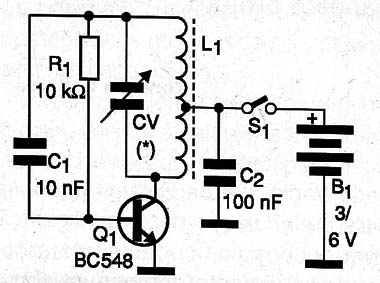
The transmitter consists of a simple Hartley oscillator with a single transistor, whose frequency is determined by the coil L1 and the adjustment of the variable capacitor CV.
C1 and R1 form the feedback loop to the signal that keeps the oscillations. C2 decouples the source.
The signals are emitted primarily by a ferrite coil with no need for antenna. As the coil has a certain characteristic of directivity in the irradiation, it helps to make hardest the game.
The emitted signals are continuous wave (CW), ie only the RF carrier that is tuned to a common AM radio, appearing on the speaker as a kind of "whistle" easily identifiable between stations.
The low consumption of the circuit ensures good life for the batteries. In figure 1 we have the diagram of the transmitter.
As it is fairly simple assembly, indicated to beginners, we suggest using a terminal strip, with the arrangement of components shown in Figure 2.
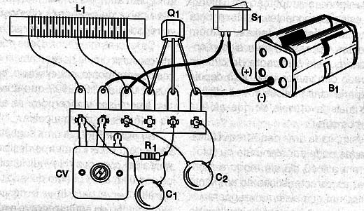
The coil is wound on a ferrite rod of approximately 1 cm in diameter and 15 to 25 cm long, consisting of 50 + 50 turns of enameled wire 28 or near.
The variable capacitor is found in any old AM radio. The transistor allows equivalent and the capacitors may be either ceramic as polyester.
To test the device, plug in its vicinity an AM radio (medium wave) tuned to a free frequency around 1200 kHz. Set CV to capture the strongest signal.
To play, tell your friends you must be equipped with AM radios and what is the approximate frequency of the transmitter signal.
Then hide the transmitter on and begin the game. Each participant should explore the site with your tuned transistor radio in the indicated range to find the transmitter signal and due to its power, locate it.
Tell your friends that you need to move constantly in tune, because in addition to the small variations that occur in their own radios, the transmitter shows floats in its frequency moving it constantly.
Usually the signals are captured when the receivers approach the distances from 3 to 6 meters from the transmitter. Do not hide the transmitter inside objects or metal cabinets because these materials block the signals.
Q1 - BC548 - General purpose NPN transistor
L1 - Coil - see text
CV - variable capacitor - see text
S1 - Single switch
B1 - 3 or 6 V - 2 or 4 small cells
R1 - 10 k Ω x 1/8 W - resistor - brown, black, orange
C1 - 10 nF - ceramic capacitor or polyester
C2 - 100 nF - ceramic capacitor or polyester
Miscellaneous:
Terminal strip, battery holder, box mount, wire, solder, enameled wire, ferrite rod, etc.


