This project aims to show how capacitors can store electric charges. To achieve this purpose, we will charge a capacitor with a high voltage, about 150 V (110/127 VAC power line) or 300 V (220/240 VAC power line). To charge the capacitor, we need a DC power supply, since the capacitors don’t charge with AC voltage. A very simple power supply will be built for this purpose.
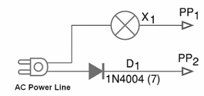
This power supply uses only a diode and an incandescent lamp. Then, with the charging circuit and the charged capacitor we will perform some experiments. Figure 1 shows the schematics for the supply used in this experiment. Observe that it is assembled on plastic or another other material with good isolation properties.
The placement of the lamp and diode on a base is shown in figure 2.
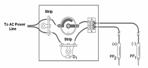
The probes can be common types as found in Multimeter, or you can build them using nails and adhesive band. Take care with this part since the probes are connected to the AC power line. Any accidental touch can cause dangerous shock hazards.
A common socket for lamps is used in the project. The diode can be a 1N4004 if the AC power line is 110/117 or 127 V. A 1N4007 should be used if the AC power line voltage is 220/240 V. The incandescent lamp can be rated in the range between 5 and 40 W. Since the device presents danger of shock, it can be handled only by adults with experience with this kind of circuit.
For the demonstrations we have two possibilities. One of them consists in making the charge of a common capacitor having values between 100 nF and 1 ?F by touching its terminals to the probes. In the case of an electrolytic capacitor, you must carefully observe the poles. Figure 3 shows how this can be made.
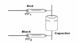
The capacitors suitable for this experiment may have a working voltage of 200 V or higher if the AC power line voltage is 110/117/127 V and 350 V or higher if the AC power line voltage is 220/240 V. Do not touch the capacitor’s terminals when charged! A heavy shock can be the result.
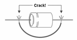
After the charging you can touch one terminal to the other. A high crack will be heard and, if you look carefully, you will see a spark, as shown by figure 4.
Another interesting experiment is the one illustrated by figure 5.
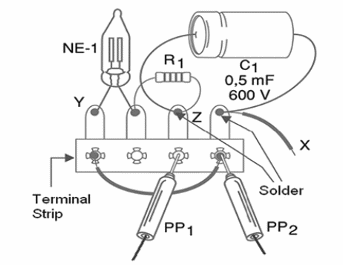
This figure shows a discharge circuit with visual indication using a neon lamp. The time constant of the RC circuit (R1-C1) determines how long the lamp will glow after the capacitor is charged by the probes.
The neon lamp glows starting from 60 to 80 V and turns off when the voltage falls bellow these values. Depending on the resistor and the capacitor, the lamp can glow for several minutes. A timer can be designed with this circuit as basis.
An interesting upgrade to this circuit is adding a 4.7 M? Potentiometer in series with R1 (replaced by a 220 k ? resistor). You can adjust the time the lamp glows during the discharge by converting the circuit into an adjustable timer.
Competition:
- Give a prize to the builder who presents the project that keeps the lamp glowing by the longest time interval.
A) Charger circuit
X1—Incandescent lamp 5 to 40 W—voltage according to the local AC power line
D1—1N4004 (110/117/127 V) or 1N4007 (220/240 V)
PP1, PP2—probes– see previous text
C1—470 nF or 1 uF—200 or 400 V polyester capacitor—see previous text
Other:
Socket for the lamp, power cord, plastic or wooden base, terminal strip, wires, solder.
B) Neon Lamp Circuit
NE-1—Common neon lamp—NE-2H or equivalent
R1—1 MΩ x 1/8 W—resistor—brown, black, green
C1—470 nF to 10 ?F x 200 V (110 V) or 400 V (220 V) - electrolytic capacitor
Other:
Terminal strip, wires, solder, etc.


