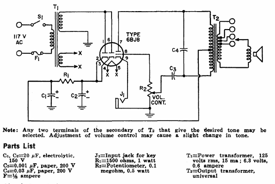
This circuit was found in the RCA Tube Manual (1970).
Circuit Description
Thís code-practice oscillator operates from a 117-volt ac power line.
When ON-OFF switch S1 is closed, the 117-volt ac input power is stepped up to 125 volts across the upper secondary winding of power transformer T1 and ís stepped down to 6.3 volts across the lower secondary winding.
The 6.3-volt winding provídes the operating power for the heater of the 6BJ8 twin diode-tride used in the circuít.
The diode sectíons of the 6BJ8 are connected to operate as a síngle diode in a half-wave rectiñer circuit that converts the ac power across the 125-volt windíng of T1 to dc operatíng power for the 6BJ8 triode section.
Thís triode sectíon ís used as the amplífier tube in a símple audio-oscillator stage.
Operatíon of the oscillator stage is controlled by a telegraph key, which ís connected into the circuit by means of jack J1.
When the key is closed, the triode section of the 6BJ8 supplíes energy to the oscillator resonant circuit formed by capacitor C3 and the eífective inductance of the prímary of output transformer T2.
Thís circuit then resonates to produce an audio signal that is coupled by transformer T2 to the speaker to produce an audible indication of the keying.
Positive feedback to sustain oscillation is developed by the autotransformer action of the tapped primary of transformer T2.
Output transformer T2 is a universal type which contains multiple taps on the secondary winding.
These taps enable the transformer to match the oscillator output impedance to different values of speaker voice-coil impedance.
The speaker impedance and transformer terminals used, however, affect the effective inductance in the primary of T1 and, thus, the tone of the audio output.
Volume-control potentiometer R2 adjusts the level of the audio output.
Adjustment of potentiometer R2 varies the loading on the oscillator resonant circuit and may also cause a slight change in the tone of the a'udio output.


