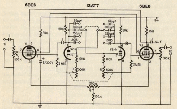
This circuit, found in an old publication about tubes, consists of two gated amplifiers channels (tubes V1 and V3) working with a common plate resistance and a multivibrator (V2) producing a sqare wave to control the alternate operation of the input channels. Altough the two input signals Y1 and Y2 are applied to the modulator grids of the mixer tubes V1 and V3, the square wave injected with inverted phase into the oscillator grids, to key one tube while the other is inoperative. The repetition frequency of the multivibrator is adjustable by steps by a bank of capacitors. and a dual potentiometer R allows for line control. To facilitate identification of similar waves, trace separation is generally provided. In the circuit described this is accomplished by potentiometer Re by varying the bias of VI and V3 in opposite directions. This varies the dc plate current of the tubes and the resultant dc voltage component is transmitted by the coupling capacitor. Acting upon Rn this raises one trace and lowers the other.


