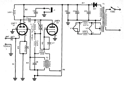
This circuit was originally published in a Popular Electronics magazine in the 1960s, consisting of a super-regenerative receiver for the VHF range. In addition to the tubes the only critical component is the transformer, which can however be replaced by a self-transformer (see article sources for valves on the site)
Coils are frequency dependent, 2, 3 and 4 wire coils 22 to 26 with 1 cm in diameter without core can be used to cover the 50 MHz to 150 MHz bands, including the aviation range.
The antenna is of the telescopic type, although an external antenna can be used and the output is made in a high impedance headphone. For loudspeaker playback, you can use an external speaker.
Material:
C1 - 1 nF - ceramic
C2a, b and c - 20/40/60 uF x 250 V - electrolytic
C3-7 pF - ceramic
C4 - 220 nF - polyester
C5 - variable 2-20 pF (taken from FM radio)
C6 - 4.7 nF - ceramic
C7-22 pF - ceramic
C8-10 nF - ceramic
R1, R3 - 330 ohm x ½ W
R2 - 5k6 - ½ W
R4 - 47 k x ½ W
R5 - 7.5 M x ½ W (8.2 M)
R6 - 25k x ½ W
R7 - 2k2 x ½ W
XRF1 at 4 - 100 uH
D1 - 1N4007
T1 - 150 V x 25 mA and 6.3 V
T2 - Transformer with 1: 3 turns ratio - audio
Miscellaneous:
Chassis, sockets for valves, button for variable, wires, solder, etc.


