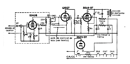
The circuit presented was found in a publication of the 70's, characterized by the use of a mechanical delay line. This line can be manufactured with a long spring.
The delay line consists of a spring having an exciter coil which causes it to vibrate with the audio signal. At the other end there is a magnetic pickup that acts as a transducer sending the signal to an audio amplifier.
The low-power audio amplifier has a 50L6 output at the output that supplies a few watts to a small speaker.
Valve filaments are connected in series and directly to the power grid, and this design does not require a power transformer.
The output transformer is 2 to 5 k of primary type, adapting to the high impedance of the valve.
In figure 1 we have the block diagram of the apparatus.
In figure 2 we have the complete diagram of the mechanical delay line for echo production.


