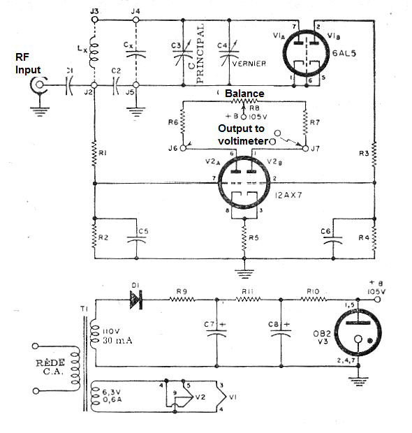
We find in an old documentation, from 1966, the interesting circuit of a Q factor meter that employs three tubes two common (double diode and double triode) and a voltage regulating tube.
The circuit described measures the quality factor of a coil, that is, its selectivity when used in a resonant circuit. Applying an RF signal to the input we scan a range of frequencies with the coil in a resonant circuit and with the measurements obtained on a voltmeter we raise the selectivity curve of the coil.
The circuit has its power source with a 110 V x 20 mA transformer which is one of the critical components of the design. See in our article Sources for Tubes Devices how to obtain an alternate source for this project.
Description of components:
R1, R2, E3, R4 - 3.3 M ohm x ¼ W
R5 - 4.7 k ohm x 1/4 W
R6, R7 - 220 k ohm x ¼ W
R8 - 47 k ohm x 1/8 W
R9, R10 - 100 ohm x ½ W
R11 - 4.7 k ohm x 1 W
C1 - 10 nF - ceramic for 100 V
C2 - 4.7 nF - ceramic for 100 V
C3-10 - 410 pF - variable
C4 - 3-15 pF - variable
C5, C6 - 100 nF x 100 V - ceramic
C7, C8-30 + 30 uF x 150 V - electrolytic
D1 - 1N4007 or equivalent
In figure 1 we have the complete diagram of the apparatus.


