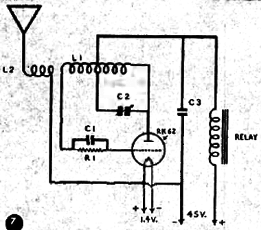
This circuit operates in the range of 60 MHz and uses two power supplies: one for the heaters and the other for the +B. The circuit was found in the Electronic Experimenter Magazine in a edition of 1950. L1 is formed by 10 turns and L2 3 turns of 14 AWG wire on a form with ½”. C1 is 100 pF, C2 is 15 pF and C3 is a 5 nF capacitor.


