Features
Range: 150 to 300 ft
Power supply voltage: 3 to 6 V (2 or 4 AA cells)
Frequency range: 88 to 108 MHz (or VHF)
Number of transistors: 1
This small transmitter can be installed in a small plastic box no larger than a cigarette pack.
It can be used as a wireless bug, picking up conversations when hidden in some object near the people who are under surveillance.
If coupled with a FM receiver installed in the same box, a pair of these devices can be used as walkie-talkies in bilateral communications.
The signals can travel up to 150 ft (in an open field) if the circuit is powered from 2 AA cells and up to 300 ft if the circuit is powered from 4 AA cells.
Any FM receiver can be used to tune the signals at a free point in the 88 to 108 MHz band.
It is important to observe that the signal range is affected by solid objects, such as large metallic structures, which can block part of the signal.
Assembly
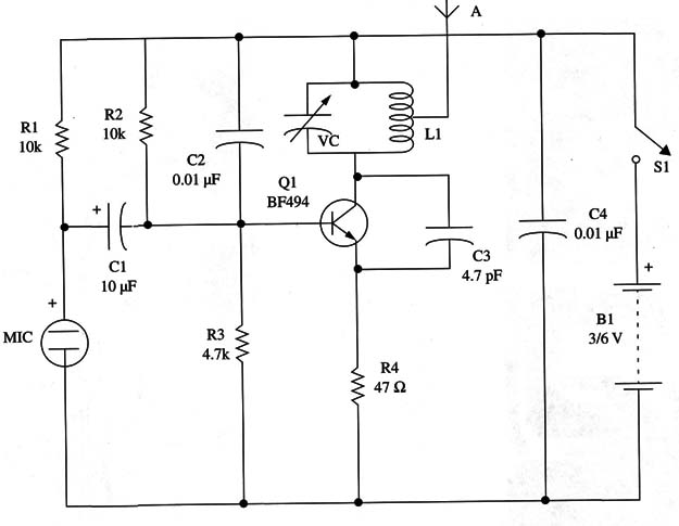
Figure 1 shows the schematic diagram of this simple FM transmitter.

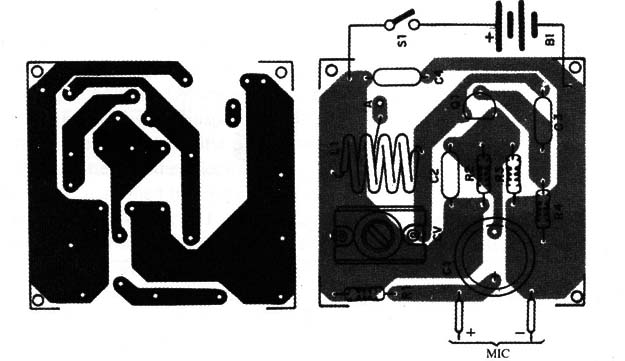
The components can be assembled on a small printed circuit board as shown in Fig. 2.

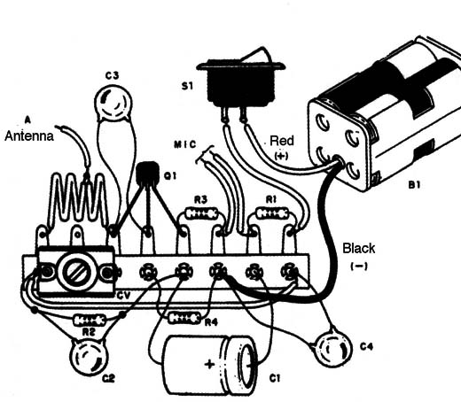
But, as it is very simple and not critical, it can also be assembled on a terminal strip as Fig. 3 shows.

Of course, both versions can be installed in a plastic box, which makes for easier transport and additional operational capabilities.
We can even recommend this as a first project for a reader who has never before assembled a transmitter or other electronic project.
The coil L is formed by four turns of AWG 22 or 24 wire without a solid core (air core) with a diameter of 1 cm.
You can even use a common piece of solid plastic-covered wire for this purpose if AWG enameled wire is not readily available.
The antenna is wired to a tap in the second turn, starting from the collector side of the transistor, and consists in a piece of solid wire 10 to 30 inches long.
If a short antenna is used, it can be wired directly to the transistor’s collector.
You can also use a telescoping antenna scavenged from any nonfunctioning transistor radio.
Don’t use larger antennas or external antennas, as these can produce interference in nearly all FM and TV receivers or cause circuit instability.
Any trimmer capacitor with capacitances in the range of 10 to 30 pF can be used for this project.
This component is not critical; if the correct frequency is not obtained, you can simply change the number of turns in the coil.
The capacitors must be ceramic types.
Many substitutes for the specified transistor can be used. Types such as the BF495, 2N2222, 2N2218, and many others can be used experimentally.
Any small RF or high-frequency NPN silicon transistor can be used.
You only have to observe the terminal placement if they are not equivalent, as in the BF494.
The electrolytic capacitor must be rated to 6 WVDC or more, and the resistors are 1/8 W or 1/4 W, 5% types.
The reader must also observe the position of the battery holder’s wires, as this is a polarized component.
It is recommended that you do not use a metallic box to house the unit.
Operation
Place near the transmitter 2 to 5 ft away from any FM receiver tuned to a free point in the FM band.
Turn on the transmitter and adjust the trimmer until the signal is picked up by the receiver.
If you are very close to the receiver, and it is sensitive enough, acoustic feedback will be produced in the form of a loud whistle.
Reduce the receiver’s volume to stop the feedback.
Then, speaking directly into the microphone, your voice will sound loud and clear from the receiver’s loudspeaker.
Walk away from the receiver, carrying the transmitter while speaking into the microphone.
If the signal disappears as soon as you walk a few feet away, you probably are tuning in a spurious signal rather than the intended frequency.
Adjust trimmer again until you find the strongest signal.
For the best performance when using the transmitter, stay away from large metallic objects and keep the antenna in a vertical position when speaking. Don’t shake the transmitter when you are talking into it.
LISTA E MATERIAIS
Semiconductors
Q1- BF494 or equivalent small signal RF transistor
Resistors (1/8 W, 5%)
R1, R2 10,000 Ω -brown, black, orange
R3 - 4,700 Ω -yellow, Violet, red
R4 - 47 Ω -yellow, Violet, black
Capacitors
C1 - 10 nF/6 WVDC electrolytic
C2 - 0.01 µF ceramic
C3 - 4.7 pF - ceramic
C4 - 0.1 µF - ceramic
CV common trimmer (see text)
Additional Parts and Materials
MIC - electret microphone (two terminals)
L1 - coil (see text)
B1 – 3 or 6 V,2 or 4 AA cells
S1 - SPST toggle or slide miniature switch
Printed circuit board or terminal strip, battery holder, plastic box, solid wire to the antenna, wires, solder, etc.


