NOTA D AUTOR
Note: this project was published in a Brazilian magazine and them transleted into English to be part of one of my books.
Features
Power supply voltage: up to 12 Vdc
Frequency range: 88 to 108 MHz
Range: several miles
Number of transistors: 3
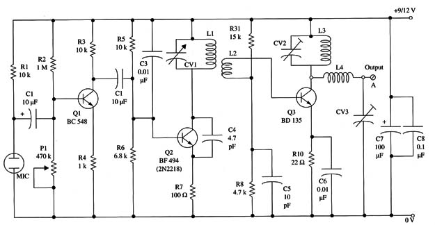
This transmitter uses three transistors. Two are used to form two high-frequency stages, and the third is used as an audio ampliñer in the modulation stage.
The circuit needs three adjustments.
Two are made using trimmer capacitors that act on the high-frequency signals to achieve maximum power output, and the other is made with a trimmer potentiometer.
The trimmer potentiometer adjuststhe audio input stage to obtain better performance according to the magnitude of the modulation signal.
An external antenna can be used under the conditions described in other articles in this section.
With an external dipole, the signals can be sent distances up to several miles over an open field.
For experimental purposes, we recommend the use of a telescoping antenna with ranges between 15 and 40 inches or a piece of wire with the same length.
Figure 1 shows the schematic diagram of this transmitter.

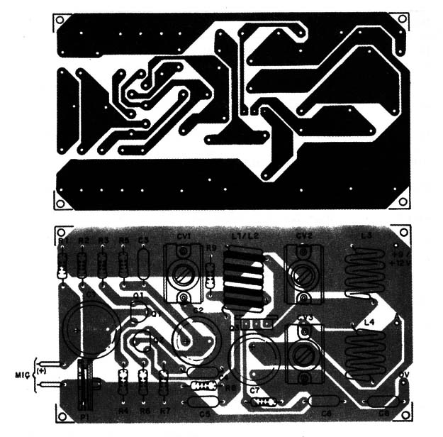
The components placement on a printed circuit board is shown in Fig. 2.

All of the coils can be wound on a pencil using AWG 18 to 22 enameled wire (or even plastic-covered wire). The coils must have the following number of turns:
L1 -4 turns
L2 - 3 turns interlaced with L1
L3 - 4 turns
L4 - 5 turns
Any plastic or porcelain trimmer capacitor with capacitances in the range of 2-20 to 4-40 pF can be used.
The differences between these trimmer capacitors and other component tolerances can be compensated by changing the number of turns in L1 and L3.
All capacitors except C1 and C2 are ceramic disc or plate types.
C1 and C2 are electrolytic capacitors rated to 16 WVDC or more.
The circuit can be powered from supplies ranging from 6 to 12 V.
If a 9 to 12 V supply is used, Q3 must be mounted on a heat sink.
Equivalents of transistor Q3 are the BD137 and BD139.
After adjusting CV1 and CV2 to get the best performance (high signal output), you must also adjust CV3 to match the output impedance with the antenna impedance to broadcast a strong signal into space.
Use a field strength meter to make this adjustment.
When applying an audio signal to the input, you also must adjust P1 to find the best audio reproduction, avoiding distortion due overmodulation.
For operation between 50 and 80 MHz, change the coils to the following:
L1 - 5 or 6 turns
L2 - 4 turns interlaced With L1
L2 - 5 or 6 turns
L3 - 8 turns
The wires and the form remain the same.
The only component change is to C4, which must be increased to 10 pF.
Semiconductors
Q1 - BC548 or equivalent general-purpose NPN silicon transistor
Q2 - BF494 (6 V) or 2N2218 (12 V) - NPN silicon transistor
Q3 - BD135 or equivalent medium-power NPN silicon transistor
Resistors (1/8 W, 5%)
R1, R3 - 10,000 Ω -brown, black, orange
R2 - 1,000,000 Ω -brown, black, green
R4 - 1,000 Ω - brown, black, red
R5 - 10,000 Ω -brown, black, orange
R6 - 6,800 Ω - blue, gray, red
R7 - 100 Ω - brown, black, brown
R8 - 2,200 Ω - red, red, red
R9 - 15,000 Ω -brown, green, orange
R10 - 22 R X 1 W - red, red, black
Capacitors
C1, C2 - 10 µF/12 WVDC electrolytic
C3 - 0.01 11F ceramic
C4 - 4.7 pF ceramic
C5 - 10 pF ceramic
06 - 0.01 µF ceramic
C7 - 100 µF/ 16 WVDC electrolytic
C8 - 0.1 µF ceramic
CV1, CV2, CV3 trimmers (see text)
Additional Parts and Materials
L1 to L4 coils (see text)
MIC electret microphone, two terminals, printed circuit board, power supply, plastic box, heat sink to Q3, Wires, solder, etc.


