Note: this project was originally published in a Brazilian magazine and them translated into English to be part of one of the autror´s book in USA.
Features
Power supply voltage: 3 to 9 Vdc
Frequency range: 3 to 15 MHz
Range: 100 ft
Transmission mode: CW (continuous wave)
This small transmitter sends a signal in the shortwave band between 3 and 15 MHz, depending on the selected coil.
The circuit can be used in emergency situations or for demonstrations.
Depending on the antenna used and the receiver’s sensitivity, the signals can be received at distances up to several hundred feet.
As this is an experimental project, one of the suggested uses is for a science fair to demonstrate how wireless telegraphy operates.
The basic circuit uses a BF494 and is powered from a 3 to 6 V supply, but it can be altered to use a BD135 or 2N2218 and be powered from a 12 V supply.
With these changes the power will be increased and also the range.
How It Works
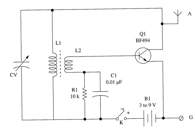
The circuit is formed by a one-transistor oscillator where the frequency is determined by L1 and CV.
The high-frequency transformer secondary (L2) provides the necessary feedback to keep the transistor in oscillation.
R1 is the component that biases the transistor, and it can be altered within a wide range of values.
The reader can experiment with values in the range between 2,200 and 22,000 Ω.
The antenna is connected to the transistor’s collector. For best performance,
good ground connection is important.
For experimental purposes, the antenna can be a piece of plastic-covered wire 10 to 40 ft long, and the ground connection can be made to any large, metallic object that is in electrical contact with the ground.
Assembly
Figure 1 shows a schematic diagram of this shortwave experimental transmitter.

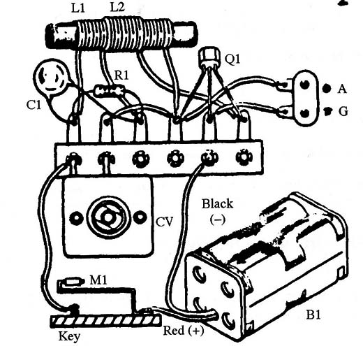
Because the circuit is very simple, the components can be mounted on a terminal strip as chassis.

The coils are wound on a small ferrite core 3 to 6 in. long.
The diameter can be in the range between 1/4 and 1/2 in.
L1 is formed with 30 turns of AWG 22 to 28 enameled wire, and L2 is formed with 10 turns of the same wire for operation in the range between 3 and 7 MHz.
For operation between 7 and 15 MHz, L1 is formed with 10 to 12 turns and L2 with 4 to 6 turns of the same wire. Note that L2 is wired over L1.
If the circuit doesn’t oscillate when you power it on, invert one of the coils.
The power supply consists of four AA cells in the basic version, but the circuit can operate from 3 to 9 V supplies.
Any variable capacitor with capacitances ranging between 120 and 360 pF can be used for this circuit.
For the basic version, you can use the BF494, but you can get more power with transistors such as the BD135 and TIP31.
But when using these transistors, you must verify the terminal positions, as they are different.
These transistors must be mounted on small heat sinks if the circuit is powered from 9 to 12 V supplies.
The morse key can be a homemade type as shown in Fig. 4.18.
A metallic blade is bent to touch a metal contact (a screw, for instance), and both are affixed on a wooden base.
Another noncritical component is the ceramic capacitor C1.
The reader can experiment with values between 2,200 pF and 0.022 µF for this component.
The antenna is a piece of plastic-covered wire 6 to 60 ft long.
The ground connection is very important for increasing performance.
Using the Transmitter
Near the transmitter, place an SW receiver tuned to a free frequency in the range determined by the coil.
Press the Morse key and tune the signal by adjusting CV1.
For this circuit to have any practical use, the reader must know Morse code.
With this device, you can conduct a demonstration of how a traditional telegraphic system works as well as this wireless one.
You simply have to explain how words are translated into Morse code.
Explain how this is accomplished.
Morse code table is given in the Appendix at the end of this book.
Semiconductors
Q1- BF494, 2N2218, BD135 or equivalent NPN silicon transistor (see text)
Resistors
R1 - 10,000 Ω -brown, black, orange
Capacitors
C1 - 0.01 µF ceramic
CV variable capacitor (see text)
Additional Parts and Materials
L1, L2 - coils (see text)
K - Morse key (see text)
B1 - 3 to 9 V - AA cells, battery or power supply (see text)
Terminal strip, battery holder, ferrite core, antenna, Wires, solder, etc.


