Note: this article is part of the book Science Fair and Technology Education Projects published in USA by the author.
Since a neon lamp needs at least 80 V to light up and we want a safe operation for the system, we adopted as solution the use of two transformers. One of them is used to turn down the AC power line voltage to 6 V.
This voltage can’t cause any shock and in its circuit is inserted the Morse key. The second transformer turns the voltage up again, to be transmitted to the remote neon lamp. Increasing the voltage is very important to extend the range of the system.
High voltages are not affected by the length of the wires, like the low voltages are. Using a plastic covered wire you can extend the communications up to 1,000 meters. The basic principle of the communication is the same as the one described in the anterior project. A short pulse of light is a point and a long pulse is a dot.
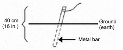
Figure 1 shows how the reader can place a metal bar into the soil to make the current return through the ground and then use only one wire to connect the stations.

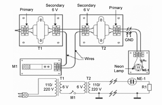
Figure 2 shows the basic mounting for the Long Range Telegraph.

T1, T2 — Power transformers — primary 110/117/220 or 240 V — secondary 6.3 V to 12 V x 250 to 600 mA.
M1—Morse key—manipulator
NE-1—Common neon lamp—NE=2H or equivalent
R1—100 k ohm x 1/8 W—resistor (brown, black, yellow)
1 wood or plastic base for the neon lamp
3 pieces of plastic covered wire 20 cm long
1,000 m of plastic covered wire, or according to the distance between stations
2 metal bars 30 to 100 cm long (any metal)
Other:
Solder, terminal strips with screws, solder, etc.
The holder for the neon lamp depends on the type used. Some types can be placed in screw bases as common lamps and others have two terminals to be soldered on a circuit. This type can be soldered on a terminal strip. Find a wet place to insert the metal bar for the ground circuit. A two way communication system is shown in figure 3.

This circuit uses a push-to-transmit switch. This switch must be placed in a position that depends on the transmitting or receiving operation. So, when one station ends a sending message it must finish the message with a signal to pass the switch to the transmitting mode. The Morse Code has a special symbol for this task. The complete Morse Code is given bellow.
Morse Code
The alphabet
.- A --. G -- M ... S -.-- Y
-... B .... H -. N - T --.. Z
-.-. C .. I --- O ..- U
-.. D .--- J .--. P ...- V
. E -.- K --.- Q .-- W
..-. F .-.. L .-. R -..- X
Numbers
.---- 1 -.... 6
..--- 2 --... 7
...-- 3 ---.. 8
....- 4 ----. 9
. .... 5 ----- 0
Punctuation marks
Point (.) .-.-.- (AAA)
Comma (,) --..-- (MIM)
Question-mark (?) ..--.. (IMI)
Colon (:) ---... (OS)
Hyphen (-) -....- (BA)
At-sign (@) .--.-. (AC)
Error ........
End of Message (AR) .-.-.-.
End of transmission (SK) ...-.-
Competition
The same as proposed in the previous project: finding out who the fastest is when transmitting and receiving a message


