Note: this project is part of y book Science Fair and Technology Education Projects published in USA.
A competition can be organized having the signal transmitted by this circuit as reference. Place the transmitter in a hidden location and ask for the competitors to find the transmitter following the signal with their portable radios. The winner is the one who finds the transmitter first.
In Mechatronics, the transmitter can be used to locate a mobile robot.
The transmitter has a range up to 200 meters, depending of the local conditions, like the presence of metallic structures encumbering the propagation of the signal.
The circuit is powered by common cells that can keep it operating during a few hours, enough to perform the experiment. Another interesting application is as a wireless alarm. Replacing S1 by a sensor, the transmitter can start the transmission when a remote event occurs, for instance, the presence of an animal inside a trap.
The trap, or many traps at the same time, can be monitored from a secure distance for experiments in natural sciences.
The transmitter uses common parts and no critical elements that can make building it difficult by people without experience. Everything the reader needs to implement this transmitter is to know how to project and build a printed circuit board (PCB).
Characteristics:
- Power supply voltage: 6 or 9 V (cells or battery)
- Range: 50 to 200 meters (depends on local conditions)
- Frequency range: 88 to 80 MHz (FM Band)
- Number of amplification stages: 1
How it Works:
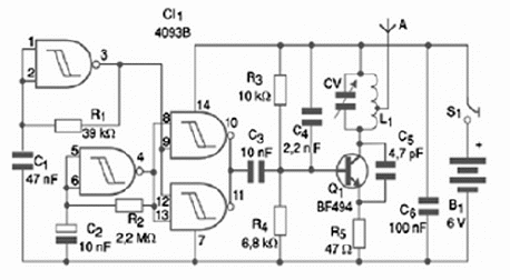
Two gates of a 4093 CMOS integrated circuit are used as oscillators in this circuit. One of them produces the audio tone and the other the interval between the tones. The audio tone has its frequency determined by R1 and C1.
The reader is free to change the values of these components by finding the best tone to the transmission. The second gate has its frequency determined by C2 ad R2.
These components can also be altered according to the reader’s preferences. We suggest the reader to try changing those components to optimize the project.
The signals produced by the two oscillators are combined in a third gate of the 4093 where we obtain, in the output, a train of pulses. This train is applied to the transmission stage that is formed basically by a transistor. The frequency of the transmission stage is determined by L1 and CV.
Adjustments in CV allows the reader to find a random point in the FM dial of a receiver, avoiding the local stations to interfere in the transmitter signals. The feedback that keeps the oscillator running is given by the 4.7 pF capacitor. The high frequency signals produced by this circuit are converted into radio waves in the antenna.
The range will depend of the antenna length, but we do not recommend the maximum value to be over 40 cm. Long lengths will cause the circuit to operate in an erratic mode.
Building the Transmitter
The complete schematics diagram for the transmitter is in figure 1.

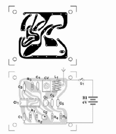
Figure 2 shows how the components can be placed on a printed circuit board (PCB).

The resistors are all 1/4 W or 1/8 W types rated to 5% of tolerance. The capacitors are ceramic or other type if indicated. The core-less coil is formed by 4 turns of 22 AWG wire with a diameter of 1 cm.
The power supply consists in 4 AA, C or D cells. It is not recommended the use of a 9 V battery since the power drain is high, reducing its life.
The transistor can be replaced by many equivalents, like the 2N2222, 2N2218 or even the BD135. For the 2N2218 and BD135 the power voltage can be increased to 12 V, extending the range to 500 m or even more.
Using and Adjusting
Place the transmitter near a receiver tuned to a random point of the dial between 90 and 100 MHz. Afterwards, adjust the CV with an appropriate plastic or wood screw driver, tuning the transmitter until its signal is received.
Find the strongest signal, because you can get confused, tuning one or two harmonics.
The harmonics can be easily identified because they are weak, disappearing when you carry the receiver away from the transmitter. If the reader does not like the transmitted tone, he/she can change it by replacing the appropriate components. The whole circuit can be placed inside a plastic box.
Competition:
Fox Hunter—this is a competition implemented with the aid of this transmitter. Schools, Clubs and Associations can use this project as part of their recreation programs. After explaining how the transmitters operate and how to use the directivity of an antenna to locate a radio source, the professor or another person tells all the competitors to tune in their radio receivers to find the transmitter signals, and then the own transmitter. The prize can be placed with the transmitter.
Another competition could be giving a prize to the one who builds highest range transmitter.
Semiconductors:
CI-1—4093B—CMOS Integrated Circuit
Q1—BF494 or equivalent—NPN silicon RF transistor
Resistors: (1/8W. 5%)
R1—39 k ohm—red, white, orange
R2—2.2 M ohm—red, red, green
R3—10 k ohm—brown, black, orange
R4—6.8 k—blue, gray, orange
R5—47 ohm—yellow, violet, black
Capacitors:
C1—47 nF—ceramic
C2—2.2 ?F—electrolytic
C3—10 nF—ceramic
C4—2.2 nF—ceramic
C5—4.7 pF—ceramic
CV—any trimmer capacitor rated to 2-20 to 5-50 pF—not critical—plastic or ceramic
Other:
L1—Coil—see previous text
S1—SPST—on/off switch
B1—6 V—4 AA, C or D cells with holder
A—Antenna—see previous text
Printed circuit board, DIL socket for the integrated circuit, plastic box to house the circuit, wires, solder, etc.


