Features
Power supply voltage: 6 V (four AA, C, or D Cells)
Range: 150 to 600 ft
Frequency range: VHF and FM
There are many uses for radio signaling transmitters. One of the applications is to locate persons or objects. If the circuit is installed inside an object, this object can be found with the aid of a receiver equipped with a directional antenna.
An interesting game that can be played using this transmitter is called “fox hunt” by radio amateurs. The fox is the transmitter that is hidden somewhere, and the hunters are the radio amateurs equipped with receivers. The hunters must tune in the signal transmitted by the fox and locate it as quickly as possible. The winner is the first hunter to find the transmitter.
The reader can use this device to play the same game at school or while camping, with the advantage that anyone who has a receiver can tune in the signals. Any FM portable radio, Walkman®, or even a car radio can be used to chase the fox.
The basic circuit is powered from a 6 V supply (four AA cells) and can send signals to distances up to 600 ft over an open field. However, the circuit can be altered to use a 2N2218 and a 9 to 12 V power supply, thereby increasing the range.
How It Works
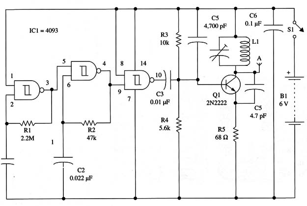
The high-frequency signals, up to 150 MHz, are produced by a transistor oscillator where the frequency is determined by L1 and CV. The feedback that keeps the oscillator running is provided by C5.
This capacitor allows us to produce higher frequencies with this circuit. Therefore, for the FM range, we use a 4.7 to 5.6 pF capacitor, but this value must be reduced if we intend to reach higher frequencies. Values between 1 and 2.2 pF are recommended for the range between 108 and 150 MHz.
For the range between 50 and 80 MHz, this capacitor must be increased to 10 to 22 pF.
The beeps used to modulate the high-frequency carrier are produced by a 4093 CMOS IC. This integrated circuit is formed by four NAND Schrnitt gates that can be used as oscillators, buffers, and/or inverters.
One of the four gates (pins 1 to 3) is used as a low-frequency oscillator to produce the beep rate. This circuit is designed to produce signals of about 0.5 Hz, as determined by R1 and CI, but these component values can be changed.
The reader can vary R1 in the range between 100,000 and 4,700,000 Ω. The beep tones are determined by a second oscillator that is wired using a second gate (pins 4 to 6).
The frequency is determined by C2 and R2. Also, in this case, resistor R2 can be varied within a wide range to change the tone. The second oscillator is controlled by the first using pin 5.
The modulated signal that consists of a series of beeps is applied to the third gate. This gate is wired as a buffer/inverter to drive the transmitter. The current drain depends on the RF transmitter stage, but for applications where it is kept in operation for one or two hours, four AA cells will provide sufficient power.
Assembly
Figure 1 shows the schematic diagram of the beep transmitter.

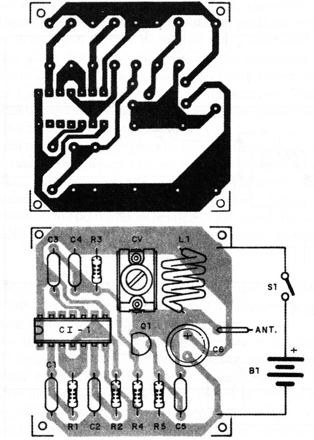
The components are placed on a printed circuit board as shown in Fig. 2.

For operation in the FM range, the coil is formed by four turns of AWG 18 to 22 enameled wire or plastic-covered common rigid wire wound around a pencil as a reference. For the VHF band between 50 and 80 MHz, the coil is formed by five or six turns. For the band between 108 to 150 MHz, the coil is formed by one or two turns of the same wire.
Any trimmer capacitor with a capacitance range between 2-20 and 4-40 pF can be used for this project. The antenna is a piece of rigid plastic-covered wire 10 to 40 in. long or a common telescoping antenna.
The circuit can be powered from four AA, C, or D cells in the basic version but if the circuit is changed to run on 12 volts, a Nicad or automotive battery must be used. With a 6 V supply current drain is about 20 mA, but this current in creases to up to 200 mA when the circuit is powered from a 12 V supply.
Adjustment and Use
Tune an FM receiver to a free point of the FM band and place it near the transmitter (3 to 4 ft). Power up the transmitter and adjust CV to tune the signal.
Be sure that the tuned signal is the fundamental one. If you move the receiver a good distance from the transmitter and the signal doesn’t disappear, then it is the fundamental.
Semiconductors
IC1 - 4093 CMOS integrated circuit
Q1 - 2N2222, BF494, or 2N2218 high-frequency NPN silicon transistor
Resistors (1/8 W, 5%)
R1 - 2,200,000 Ω -red, red, green
R2 - 47,000 Ω - yellow, violet, orange
R3 - 10,000 Ω - brown, black, orange A
R4 - 5,600 Ω - green, blue, red
R5 - 68 Ω- blue, gray, black
Capacitors
C1 - 1 µF metal film or electrolytic
C2 - 0.022 µF ceramic or metal film
C3 - 0.01 µF ceramic
C4 - 4,700 pF ceramic
C5 - 4.7 or 5.6 pF ceramic (see text)
C6 - 47 µF/ 12 WVDC, electrolytic
CV - trimmer capacitor (see text)
Additional Parts and Materials
B1 - 6 V, four AA cells (see text)
S1 - SPST toggle or slide switch
L1 - coil
Printed circuit board, battery holder, plastic box, wires, antenna, solder, etc.


