Features
Range: 300 to 1,000 ft (depending on the laser)
Modulation: amplitude
Transmitted signal: audio (200 to 10,000 Hz)
You can send Voice or music from any source (e.g., a CD player or tape recorder) over distances up to 1,000 ft using a laser beam This experimental circuit can be used to demonstrate how optical communication systems operate.
The Circuit is formed by a transmitter that uses a small laser pointer or a semiconductor laser module and a modulation system semiconductor lasers are powerful enough to send their signals over large distances (up to 1,000 ft) and can be obtained easily from many dealers.
As a sensor, the receiver uses a photodiode or phototransistor that ís sensitive enough to pick up the laser beam, even when it is located at a great distance from its source.
The project is experimental as We use an empirical method to achieve modulation. But some suggestions are offered for readers. Who wants to make further improvements in the circuit.
With changes in the modulation system, using a Kerr cell for instance, the reader will be able to transmit high-frequency signals, including Video or digital signals, from a PC serial port via the laser beam It is also possible, by adding a multiplex circuit, to transmit several audio channels simultaneously using one laser beam.
How It Works
The light beam produced by a laser (red, for instance) can be used as a carrier to transport low-frequency signals such as audio, digital data, or video.
Light is a form of electromagnetic waves, but it exhibits an ultra high frequency in the range of terahertz (trillions of hertz).
A laser is a special kind of light source. The radiation produced by a laser is monochromatic (e.g., it consists of only one frequency and is Visible as a single color) and Coherent. Because of these and other properties, a laser light beam is highly focused. The light does not spread out to form a large spot, even at great distances.
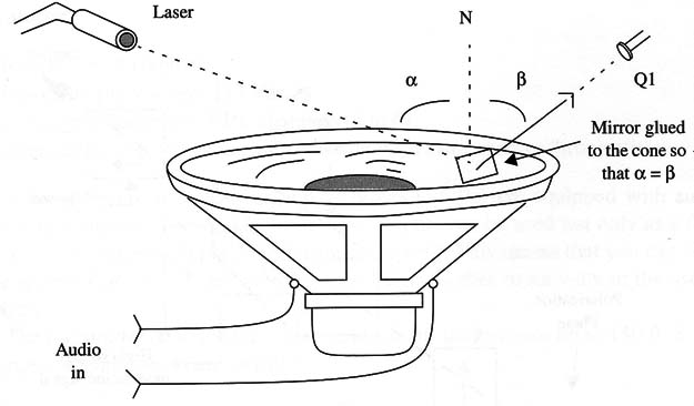
The concept here is to make a laser beam fall onto a small mirror that is placed on a loudspeakers cone as shown in Fig. 1.
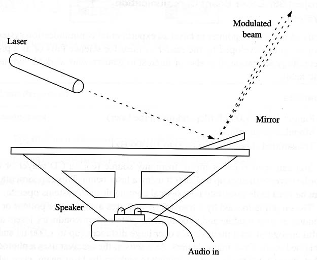
When no signal is applied to the loudspeaker, the light beam can be picked up by a sensor placed as shown in the figure. But when an audio signal is applied to the 1oudspeaker, the cones movement is transferred to the mirror.
As a result, the mirror oscillates according to the sound, changing the light beam reflection angle. The light beam oscillation is detected by the receiver, which generates a corresponding audio signal.
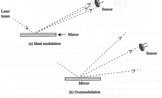
This adjustment is very critical because, if the light beam oscillates excessively, the sensor will pick up only the modulation peaks, chopping the signal.
The experimenter must experiment to find the ideal volume applied to the loudspeaker that gives good reproduction in the receiver (see Fig. 2).
The experimental system can be built using any low-power amplifier (100 mW to 1 W) and a receiver. The receiver can be any common audio amplifier or the circuit suggested below.
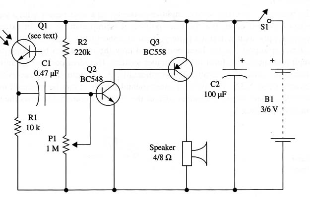
This receiver circuit uses two complementary direct-coupled transistors and directly drives a small loudspeaker. The sensor is any phototransistor or photo-diode. Using optical aids such as a convergent lens and a tube, the sensitivity can be increased and interference sources neutralized.
Assembly
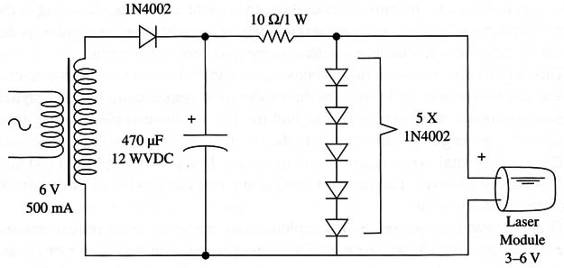
The transmitter consists of any amplifier connected to a loudspeaker with a small mirror mounted on it. For the laser pointer, it is important to use an external power supply, as it will run a battery down in a short time.
Figure 3 shows a 3 V power supply for the laser pointer and how the mirror can be affixed to a small loudspeaker to form the transmitter system.
The ideal position for mirror placement must be determined experimentally. A diagram of the receiver is shown in Fig. 4.
As this is an experimental circuit, it can be mounted on a solderless board or use a terminal strip as the chassis. Figure 5 shows the terminal strip version.
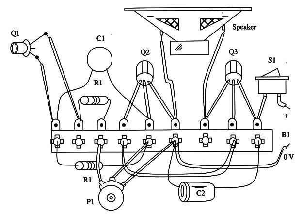
The power supply is formed by two or four AA cells, and P1 adjusts the gain of the circuit. The sensor is any phototransistor or photodiode. If you place this component inside a cardboard tube with a convergent lens, the sensitivity and directional characteristics will be increased.
Any small 4 or 8 Ω loudspeaker can be used.
Adjustments and Use
Place the loudspeaker and the laser pointer as shown in Fig. 6.
Place the receiver’s sensor in a position to receive the laser beam. The sensor can be place 10 ft or more away from the transmitter.
Turn on the amplifier and the receiver. As a signal source, you can use a CD player plugged into the transmitter input. Resistors RX are important to avoid loading the output of the CD player.
Observe that we are using the signal from the two channels at the same time, as they are mixed. Put the amplifier in a low-volume position and carefully adjust the transmitter’s amplifier to get the best sound.
As a suggestion, a Kerr cell can be used to send information via powerful laser beams such as the helium-neon (HeNe) types and others. Ranges up to several miles can be achieved when using powerful laser beams.
The Kerr cell is a piece of crystal that, when exposed to a high-voltage signal, changes the polarization angle of a light beam passing through (see Fig. 7).
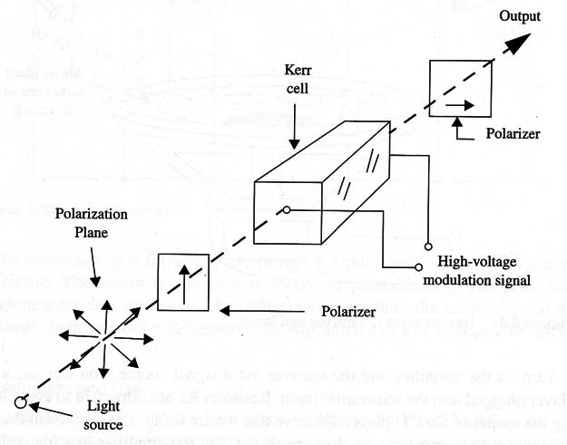
As a result, if the elements of polarization are placed before and after the cell, changes in the polarization angle will produce an amplitude modulation with the high-voltage signal applied.
(Receiver)
Semiconductors
Q1 - BC548 or equivalent general-purpose NPN silicon transistor
Q2 - BC558 or equivalent genera-purpose PNP silicon transistor
Q3 - any phototransistor
Resistors
R1 - 100,000 Ω -brown, black, yellow
R2 - 220,000 Ω - red, red, yellow
(Receiver)
P1 - 1,000,000 Ω - potentiometer
Capacitors
C1 - 0.47 µF ceramic or metal film
C2 - 100 µF/6 WVDC electrolytic
Additional Parts and Materials
S1- SPST toggle or slide switch
B1 - 3 or 6 V, two or four AA cells
SPKR - small loudspeaker, 4 or 8 Ω
Terminal strip, battery holder, plastic box, cardboard tube and lens, wires, solder, etc.


