Hertz's basic idea for receiving radio signals, then discovered, and used in his famous experiment in which he made a transmission inside his laboratory, was the spark-excited dipole antenna.
One link formed the resonant antenna approximately at the transmitter frequency, containing a gap between two beads, as shown in Figure 1.
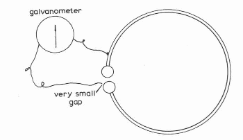
A pulse emitted by the transmitter caused a small spark in the receiver that could be observed under favorable conditions, or detected by a galvanometer as suggested by Fitzgerald in the figure.
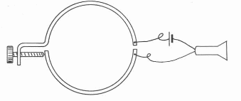
The signal detection could also be done in the manner suggested later with the use of a headset, as shown in Figure 2 according to Turpain.
The first breakthrough in receiving radio signals came with the invention of the coherer made by Professor Edouard Branly.
The phenomenon of "coherence" had already been observed in 1835 by the scientist P. Munk at the University of Lund and rediscovered in 1852 by S.A. Varley who used it in the protection of telegraph lines.
The idea is as follows: two bars of oxidized copper when in contact present a resistance of the order of 80 000 Ω. However, when we apply a voltage between them, the resistance drops to as low as 7 Ω.
The idea of the coherer is very simple: filling a glass tube with metal filings, in contact with one another they present the phenomenon of coherence, that is, an extremely high electrical resistance or an open circuit.
However, in the presence of a signal (a voltage) the resistance between the grains of metal fillings falls and the resistance falls as well.
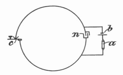
If a voltage source is used to keep the filings at the conduction limit, in the presence of the signal, the current of this source is conducted, producing a signal, as shown in Figure 3.
A simple radio receiver using coherer is shown in Figure 4.
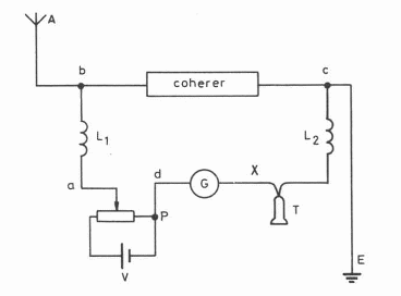
In this receiver A is the antenna, E is the ground, G a galvanometer, T an ear tone and V the battery.
The potentiometer P is set to take the voltage in the coherer to the limit.
This same principle is used in the receiver that we published using a razor and in another we used a type of steel sponge. In both, the junction of these components functions as a coherer by adjusting the conduction limit voltage to the reception of the desired signals (see ART2502 and ART2536).
Based on the same principle of the oxidized bar we have a coherer invented by Odenbach at the same time. An oxidized metal bar was supported on two conductive wires.
The conduction of the bar in contact with the wire changed in the presence of signals.
The form of the coherer had many variations in the years that followed its creation, each inventor trying to improve the performance in order to detect weak signals, since at the time there were no active devices that could amplify them.
In Figure 5 we have some coherers of the time created by well-known "inventors" of the radio.
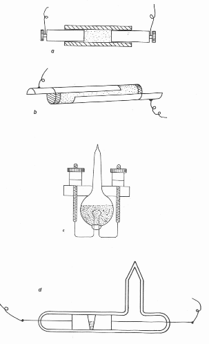
In (a) we have a Branly’s coherer, (b) a Popov’s, (c) a Lodge’s, and (d) a Marconi’s.
The great problem of these coherers was the imperfection of the contacts that made them unstable.
Various substances and metals were used by radio pioneers such as nickel (95%), mixed with silver (5%) in Marconi's case, mercury ends and several other combinations, revealing that at that time much more than a theoretical knowledge of what could occur, the inventiveness predominated.
A very interesting arrangement, showing all this inventiveness was Bottone's “coherer", created in 1910, shown in Figure 6.
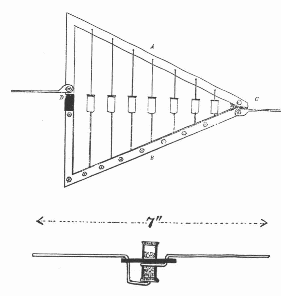
The idea was to take advantage of a possible resonance from several coherers, so that the one that had the greatest response to the signal was responsible for its conduction and consequent detection.
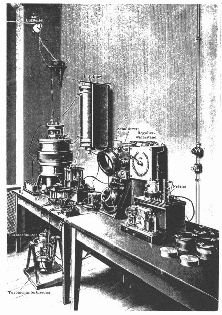
At that time the wireless telegraph stations were already common, and by the figure of the quoted book we have an idea of ??the equipment used.
Electrolytic Detectors
A type of detector that appeared after the coherers is the so-called electrolytic detector.
As the name suggests, these detectors are based on the electrical properties of electrolytic solutions, being basically of two types.
One of the detectors has low resistance in the absence of signals and the other has high resistance in the absence of signals.
Those that show low resistance in the absence of signals, increasing this resistance when the signal is detected were also called "anti-coherers".
In Figure 8 we have an illustration of the Pupin detector from 1913.
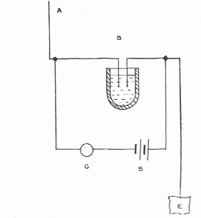
In these detectors the inventiveness was worth varying the substances used like glycerine, water, metals in suspension, etc.
In Figure 9 we have to "asswer" to an electrolytic detector invented by De Forest in a container with an active pulp.
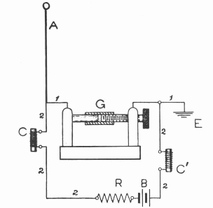
Figure 10 shows an acid detector in which the electrodes were of platinum and lead. The acid could be either nitric or sulfuric and a small voltage of a battery was applied to the electrodes.
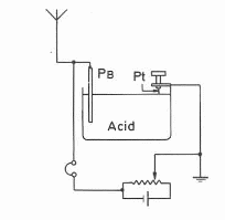
By adjusting the polarization using the the circuit potentiometer, it was possible to take the circuit to the point of detecting radio signals picked up by the antenna.
At this time the amateurs of electronics could already assemble their own radios and specialized publications gave the first practical projects.
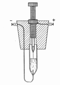
In Figure 11 we have an electrolytic detector published in an article for the homebuilder Wireless World magazine in a 1914 edition.
Magnetic Detectors
These are based on the fact that the circulation of a current through a wire, and consequently a coil, creates a magnetic field.
The current is from a signal picked up and several devices can be used to detect the presence of the field created.
In Figure 12 we have a Pierce’s electrodynamic detector from 1904.
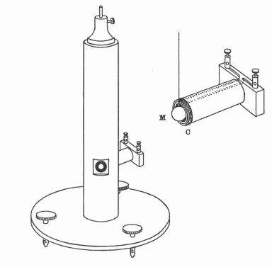
To detect the movement of a magnetized needle under the action of the field created, the most diverse optical resources were used as mirrors and microscopes.
Figure 13 shows an animation receiver where needles were automatically magnetized from time to time. This receiver was created by Fleming in 1905.
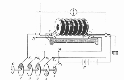
A very interesting magnetic detector arrangement was created at the same time by Bouasse which is based on the hysteresis of the magnetizable materials and is shown in Figure 14.
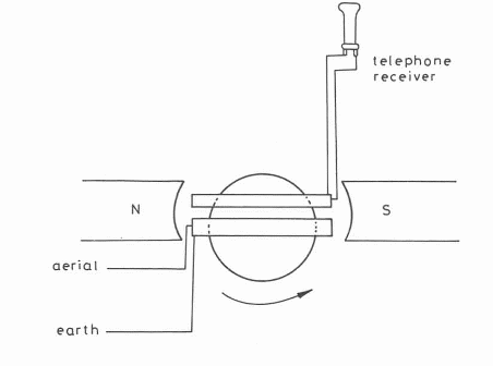
The was idea to produce a rotating magnetic field so that it interacts with a magnetic field created in a coil by the captured signal.
The signal transferred by induction to the coil with the handset would be detected.
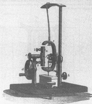
The interesting thing is that at the time the electric motors were not yet used in this type of application and a generation of the magnetic field was made turning a handle, according to the equipment of the Figure 15.
Conclusion
And there's more to come.
Before arriving at the familiar semiconductor diodes from nowadays, many other techniques were created to detect radio signals, some quite curious.
In a next article we will analyze some detectors used in the early days of the radio like the capillary detectors, thermal detectors and others.
Revised 2017


