Features
- Power supply voltage: 6 to 12 Vdc
- Frequency range: 88 to 108 MHz
- Number of transistors: 2
- Range: 1,500 ft (typical)
This transmitter can be powered from a 6 to 12 V power supply, dry cells, or a nicad battery.
The range will depend on the supply voltage. The circuit also implements an audio amplifier stage to increase microphone sensitivity.
Observe that only one transistor is used to produce the RF or high-frequency signals. The other transistor is used for the audio signals.
The reader can use this transmitter as a wireless microphone for short-range communications or as a “bug” to hear conversations in an adjacent room.
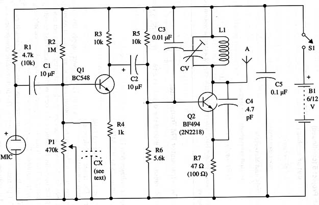
The ideal bias for the audio stage can be adjusted using a trimmer potentiometer, allowing the operator to achieve the best performance. Best results are obtained when using a 3 to 4 ft antenna. Figure 1 shows the complete schematic diagram for the transmitter.

The components with values enclosed in parentheses are indicated for a 12 V power supply.
L1 and CV are the same as used in previous projects. All capacitors with values less than 1 µF must be ceramic types. The higher-value components are electrolytic, rated to voltages as specified in the parts list.
The electret microphone can be replaced w1th a common high-impedance microphone if you remove res1stor R1.
If you want to increase the sensitivity to low-frequency sounds (bass) by cutting the high frequenc1es, you can Insert a capacitor (CX) as shown in the diagram.
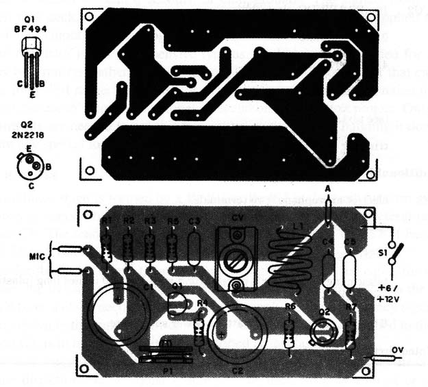
The proper value of this component 1s found experimentally, but it probably will be in the range of 0.1 to 10 µF. The components are placed on a printed circu1t board as shown in F1g. 2.

To adjust and use this transm1tter, proceed as described in projects like this described in the site.
Semiconductors
Q1 - BC548 or equivalent general-purpose NPN Silicon transistor
Q2 - BF494 or equivalent RF Silicon NPN tran31stor
Resistors (1/8 W, 5%)
R1 - 4,700 ohm - yellow, Violet, red (10,000 ohm -brown, black, orange)
R2 - 1,000,000 ohm - brown, black, green
R3, R5 - 10,000 ohm -brown, black, orange
R4 - 1,000 ohm - brown, black, red
R6 - 5,600 ohm - green, blue, red
R7 - 47 ohm - yellow, Violet, black (100 Q-brown, black, brown)
Capacitors
C1, C2 - 10 µF/ 16 WVDC, electrolytic
C3 - 0.01 µF ceramic
C4 - 4.7 pF ceramic
C5 - 0.1 µF ceramic
Cx (see text)
CV - trimmer (see text)
Additional Parts and Materials
MIC - electret microphone (two terminals)
L1 - coil (see text)
S1 - SPST toggle or slide switch
A - telescoping antenna or a piece of rigid wire 10 to 20 inches long (plastic covered)
B1 - 6 to 12 V, AA cells, nicad battery, power supply, etc.
Printed circuit board, battery holder, plastic box, wires, etc.


