We describe the assembly of a micro UHF transmitter that under proper conditions and a sensitive receiver can reach a range of more than 500 meters.
The circuit is quite critical due to the high frequency of operation, but with care can be set up by careful readers.
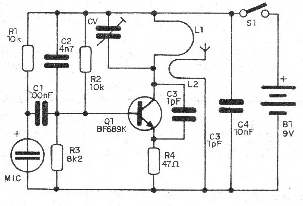
What we have is a simple oscillator with only one transistor where the frequency depends on the coil that has half turns formed by a track on the printed circuit board.
The trimmer must be of very low capacitance, to reach the desired highest frequency.
The power is supplied by a 9 V battery.
Assembly
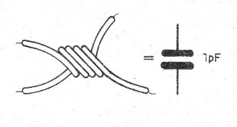
The critical component of the assembly is the 1 pF C3 capacitor that is homemade.
It consists of two pieces of wire approximately 2 cm long, assembled as shown in figure 1.

Note that the tips should be kept off.
In figure 2 we have the complete diagram of the transmitter.

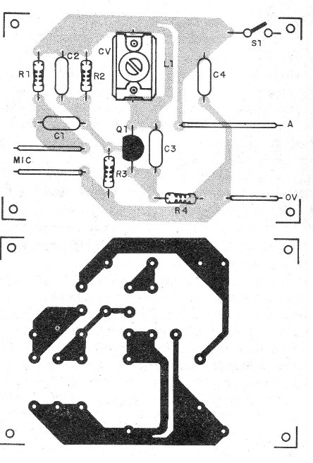
The printed circuit board for the assembly is shown in figure 3.

The capacitors must all be ceramic of good quality and the resistors are 1/8 W with any tolerance.
The microphone is a two-terminal electret and the antenna consists of a piece of rigid wire 5 cm to 10 cm long.
The trimmer can either be of the old type porcelain with a minimum capacitance of 1 to 2 pF.
To test, just have a receiver for UHF or use an old analog TV with UHF band, testing on channel 14 or 15.
Q1 - BF689K or equivalent - UHF transistor
MIC - 2-terminal electret microphone
S1 - Single switch
B1 - 9 V - battery
L1, L2 - Coils - see text
C1 - 100 nF - ceramic capacitor
C2 - 4n7 - ceramic capacitor
C3 - 1 pF - see text
C4 - 10 nF - ceramic capacitor
R1, R2 - 10 k ohm - resistors - brown, black, orange
R3 - 8k2 ohm - resistor - gray, red, red
R4 - 47 ohm - resistor - yellow, violet, black
Several:
Printed circuit board, battery connector, mounting box, wires, solder, etc.


