Features
- Mixer included
- VU meter included
- Frequency range: 88 to 108 MHz
- Range: 150 ft (typical)
- Power supply voltage: 6 V (4 AA cells)
The circuit includes a high-performance mixer and VU meter and is powered from common AA cells.
The signals can be tuned in by receivers placed at distances up to 150 ft. Of course, the short range is specified to avoid problems with the law.
The circuit is recommended for readers who are looking for a good project for a school science fair or a technology education project, or as an experimental radio station at school or home.
Latent talent for a career as a broadcast journalist or DJ can be revealed with this simple, low-cost project. School basketball or football games can be broadcast using this station.
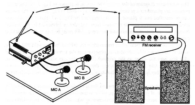
Another use for this experi- mental radio station is as a wireless microphone mixer, transmitting sounds picked up by several microphones to a powerful audio system as suggested by Fig. 1.

We can sum up this transmitter’s principal features as follows:
- Range: 150 ft
- Powered from four AA cells or supply plugged to the ac power line
- Three audio inputs with independent volume controls
- High-gain mixer stage, allowing operation with low-signal sources as microphones
- Added VU meter
- Modulation adjustment available for better performance
How It Works
The audio input circuit is formed by a mixer using a junction field effect transistor (JFET) and a bipolar common transistor.
The configuration produces a large gain from the input signals, with high fidelity. Even signals from low signal sources such as low-impedance microphones and guitar pickup transducers can be used with this circuit.
The original circuit was designed to use three inputs, but the reader is free to add more. Associated with each input, there is a potentiometer to control the signal level applied to the amplifier stage.
By adjusting the potentiometers, it is possible to fix the signal level of each input and mix them to form the transmitted signal.
For instance, you can adjust the level of a microphone signal to be higher than the level of music coming from a CD player and transmit words along with the musical background.
The signals produced by this circuit are applied to the input of a small FM transmitter using a BF494 transistor. (Notice that the signal also can be applied to the input of powerful transmitters stages, but the reader must make sure that it will not cause legal problems.
The transmitter is adjusted by CV to operate at a free point of the FM band.
The antenna is a telescoping type, 10 to 30 inches long, but a long piece of plastic-covered rigid wire can also be used.
If the reader lives on a farm or in another sparsely populated area, an external antenna can be used experimentally.
The reader can also replace the transistor with a 2N2218 and power the circuit from 9 to 12 V supplies.
Resistor R11 must be replaced by a 2 W unit. Using an external antenna, and with the modifications described above, it is possible to send the signals over distances up to a mile.
The audio output signal is also sent to a VU meter formed by transistors Q4 and Q5.
The transistors amplify the signal and apply it to a microammeter.
Two components found in this stage can be altered to obtain best performance.
R12 is chosen according to the VU meter sensitivity and can assume values between 4,700 and 47,000 ohm. Otherwise, R8 must be reduced to obtain the zero adjustment.
Of course, this stage is optional and can be omitted if the reader prefers.
The power supply is formed by four cells (AA, D, or C). If the reader prefers to use an ac power supply, it is important to provide a good filtering circuit to avoid hum and noise.
Assembly
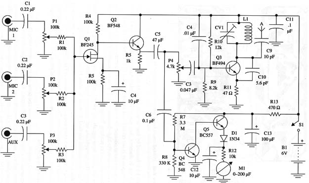
The schematic diagram of the pirate FM station is shown in Fig. 2.

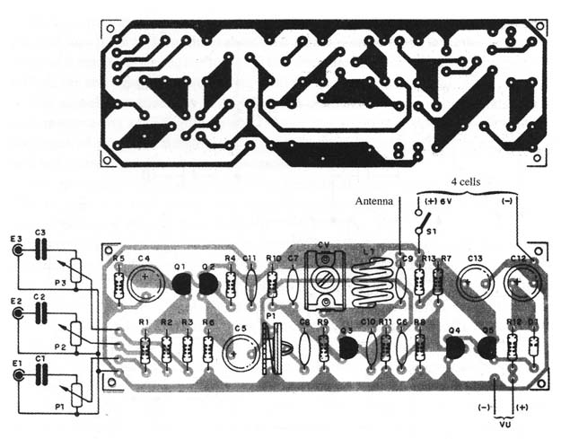
The components are placed on a printed circuit board as shown in Fig. 3.

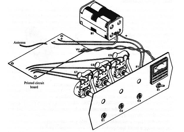
All the pieces can be installed into a plastic box as suggested by Fig. 4.

Boxes like the one used in the prototype can be obtained from a dealer or fabricated by the reader.
Notice that the potentiometers and the input jacks must be wired using shielded cable to avoid hum.
The recommended field effect transistor is the BF245, but the MPF102 can be used.
If you make this substitution, observe that the terminal placement for the MPF102 isn’t the same as the original.
The reader can also use a 2N2218 or 2N2222, but take care when placing these equivalents on the printed circuit board.
The other transistors also can be replaced by equivalents, as the circuit is not critical.
For this prototype, we use a common linear rotating potentiometer as shown in the figures but, if you prefer, it is possible to use slide potentiometers instead.
For M1 we recommend any microammeter with scale range between 200 and 500 µA. Remember that this is a polarized component, so if the needle tends to indicate negative audio levels, you must reverse the connections.
Coil L1 is formed by four turns of AWG 18 to 22 enameled wire on a coreless form 1 cm in diameter.
Any plastic or porcelain trimmer capacitor can be used.
This component is not critical, and values between 20 to 40 pF can be used.
It is important to observe the types of capacitors recommended in the parts list.
The units used in the high-frequency stage must be ceramic. The electrolytic capacitors are rated to working voltages of 12 V or more.
For the audio input signals, we use P2 or RCA jacks according to the signal sources.
The microphones are common high-impedance types. If very low-impedance microphones are used, it would be better to use a preamplifier stage.
If this transmitter is to be used as an experimental radio station, we suggest that you fabricate two extension cables as shown in Fig. 5.

These will be used to connect remote microphones. To connect tape recorders, CD players, and other signal sources, you must use appropriate cables and plugs.
Adjustments and Use
Put the cells into the battery holder and place the transmitter close to an RF receiver tuned to a free point of the FM band. The receiver must be adjusted to half volume, and you must plug a program source into the input of the radio station.
This program source can be a tape deck with a music tape or a CD player.
The signal can be picked up from the speaker or earphone outputs in those devices.
Turn on S1 in the transmitter and adjust CV1 to tune the signal to match the receiver setting. Take care to not tune in harmonics or spurious signals.
When you are receiving the signal, adjust the corresponding input potentiometer to two-thirds of its maximum, and set P4 so that you have a strong and clear audio signal in the receiver.
Then, observe whether the VU-meter is indicating the signal. Replace R8 if necessary to achieve better performance.
Radio Station Operation
To use the circuit in an experimental low-power radio station, we must keep in mind that the three potentiometers are used to determine the level of the transmitted audio signal.
Therefore, we have to plug the signal sources into the transmitter’s inputs and experiment to find the adjustment for each one that produces undistorted sound in the receiver.
To pass the signal from one source to another, you can adjust the two corresponding potentiometers at the same time. While you reduce the volume of the first source with one of them, you can use the other to increase the volume of a second source.
It is important to use a small FM receiver with an earphone as a monitor. Do not use a receiver with an operating loudspeaker.
If the microphone is placed close to the receiver’s speaker, acoustic feedback will result in the form of a strong whistle, which will interfere with your transmission.
When using the transmitter as a public address (PA) system, the loudspeakers must be located in a manner that avOids acoustic feedback, as shown in Fig. 6.
Figure 6 – Using as a PA
Also keep in mind that open-field operations allow you to transmit over greater distances than if you place the transmitter in a location where metallic structures can interfere with signal propagation.
If you don’t have a microphone to plug into your radio station, you can improvise one using a small loudspeaker and an audio output transformer as shown in Fig. 7.
Figure 7 – Using a small loudslearker as microphone
The transformer can be rated to primary impedances between 200 and 2,000 ohm.
If distortion appears when using CD players or tape recorders (when the signal is picked from the earphone output) it will be necessary to wire a 47 ohm X 1/2 W resistor in parallel with the audio output cable.
Semiconductors
Q1 - BF245 or equivalent JFET (see text)
Q2, Q4 - BC548 or equivalent general-purpose NPN silicon transistor
Q3 - BF494 or equivalent small-signal RF silicon transistor
Q5 - BC558 or equivalent general-purpose PNP silicon transistor
D1 - 1N34 or equivalent general-purpose germanium diode
Resistors (1/8 W, 5%)
R1, R2, R3 - 100,000 ohm - brown, black, yellow
R4, R12 - 10,000 ohm - brown, black, orange
R5 - 4,700 ohm - yellow, violet, red
R6 - 1,000 ohm - brown, black, red
R7- 3,300,000 ohm - orange, orange, green
R8 - 330,000 ohm - orange, orange, yellow
R9 - 8,200 ohm - gray, red, red
R10 - 12,000 ohm - brown, red, orange
R11 - 47 ohm - yellow, violet, black
R13 - 470 ohm -yellow, violet, brown
P1, P2, P3 - 100,000 ohm potentiometer
R4 - 4,700 ohm trimmer potentiometer
Capacitors
C1, C2, C3 - 0.22 µF ceramic or metal
C4, C12 - 10 µF/ 12 WVDC, electrolytic
C5 - 47 µF/ 12 WVDC, electrolytic
C6 - 0.1 µF ceramic or metal film
C7 - 0.01 - µF ceramic
C8 - 0.047 µF ceramic or metal film
C9 - 10 pF ceramic
C10 - 5.6 pF ceramic
C11 - 0.1 11F ceramic
C13 - 100 pF/ 12 WVDC, electrolytic
Additional Parts and Materials
M - 0-200 µA moving coil ammeter
L1 - coil (see text)
CV - trimmer capacitor (see text)
A - Antenna (see text)
S1 - SPST toggle or slide switch
B1 - 6V,4AA,C or D cells
Printed circuit board, plastic box, input jacks, shielded cable, wires, battery holder, knobs to the potentiometers, solder, etc.


