Features
- 12 to 15 V power supply voltages
- Current drain: up to 1.5 A
- Frequency range: 88 to 108 MHz
- Output power: 2 to 5 W
- Modulation: using varicap
- Audio input sensitivity: l'Vpp
- Output stage: class C push-pull
- Range: up to several miles
If you are looking for a high-power transmitter for experimental purposes, or even to create a broadcasting station for your home, a farm, a club, or an isolated school, this project is recommended.
Once again we must remind the reader about existing laws governing the operation of this kind of equipment. Be sure that the operation of this transmitter will not interfere with other systems or infringe on the FCC rules (or the rules that exist in your country).
This transmitter uses four transistors and operates in the FM range between 88 and 108 MHz.
It is also possible to change the coils for operation in the low VHF band between 50 and 88 MHz, but the reader must have a special receiver to tune the signals and still must be careful to observe the rules related to this kind of transmission.
The power output can rise to values up to 5 W due to the powerful push-pull stage, which uses special RF transistors.
It is also important to draw the reader’s attention to the fact that this circuit is more critical than the others previously described in this book.
Therefore, only a reader who is highly experienced with high-frequency circuits involving printed circuit board layout and tuned circuit adjustments should attempt to build this transmitter.
How It Works
When trying to diagnose problems in a nonfunctioning transmitter, is very important to know how it works.
This is one of the reasons why the “How It Works” section is included in all of these projects, and readers are advised to pay special attention.
Figure 1 shows the block diagram representing the transmitter.
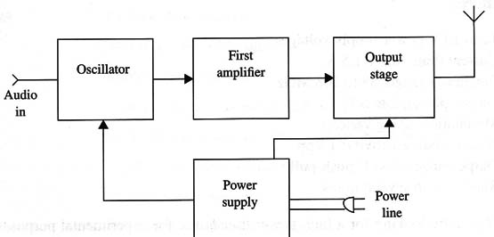
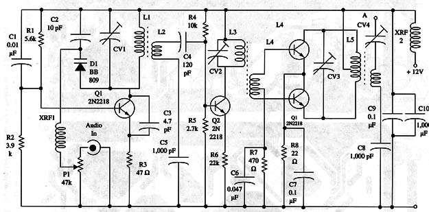
The first block represents a high-frequency oscillator where L1 and CV determine the operating frequency.
This circuit is modulated by a varicap. As described in other projects, varicaps are variable-capacitance diodes that can change the frequency of a resonant circuit by means of an audio signal (see that project for more details).
The varicap is used to modulate the high-frequency signal from an audio signal picked up from an external source.
To get the best modulation, P1 must be adjusted according to the audio source output power.
The modulated high-frequency signal produced by this circuit, between 88 and 108 MHZ, is applied to the second block, a driving stage, or first amplifier stage using a medium-power RF transistor.
The transistor is wired to the common emitter configuration with a resonant circuit as the load, plugged into the collector.
To maximize performance, it is very important to adjust the load resonant circuit to the correct frequency.
This is done by adjusting the trimmer capacitor CV2. The amplified signals are then applied to the input of a two-transistor push-pull stage. This is the third block shown in our block diagram.
L4, which picks up the signals, has a CT (center tap) placed so that there are two signals in phase opposition to be applied to the output transistors’ bases.
This means that, in Class C operation, during each half-cycle of the input signal, one transistor conducts while the other remains off.
A high-frequency stage using this configuration can generate high output powers from small input signals.
The principal advantage is that when one transistor is amplifying a half-cycle, the other does not drain any current, as it has been cut off.
The transistor chosen for this application is the 2N3866, which can drive several watts in a circuit such as this. The output signal is applied to a resonant circuit formed by LS and CV3.
Again, this resonant circuit can be carefully adjusted for better performance. CV4 is the last adjustment, matching the circuit impedance with the antenna.
This is necessary to get the better signal transference into space.
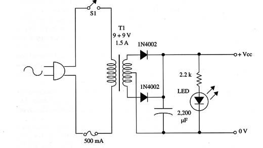
The circuit is powered from a 12 V power supply. We recommend the use of a car battery to avoid problems with noise or hum. If you prefer to power the circuit from the ac line, the power supply must include a good filtering circuit.
Figure 2 shows a power supply that may be used with this transmitter.
Assembly
The complete diagram of the transmitter is shown in Fig. 3.
The components are placed on a printed circuit board as shown in Fig.4.
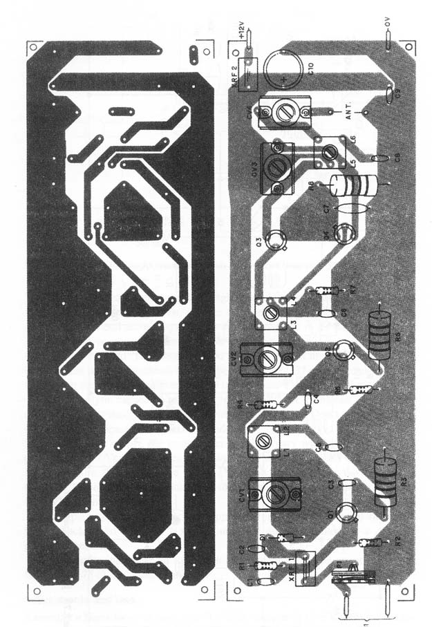
The printed circuit board layout is a very important item to be considered in this project.
The connections between components must be short to minimize capacitance losses that can affect the performance by introducing instabilities and hum.
Q1 and Q2 can be the original 2N2218 or equivalents such as the BD135. (Notice that the BD135 is an audio transistor, but it has a high transition frequency that allows high-frequency oscillation when used in circuits such as this).
The 2N3866 transistors must be mounted on heat sinks.
The coils are mounted on plastic forms such as those used in intermediate frequency (IF) and oscillator transformers.
The transformers must be mounted, and the coils are wound on plastic forms as shown in Fig. 5.
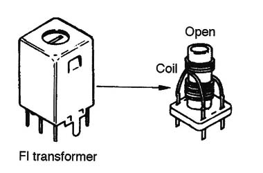
These transformers can be found in many old, nonfunctioning transistor radios and TV sets.
Extract the transformers from the original printed circuit boards and remove the metal cover carefully. Then, remove the Wire used for the original winding and wind a new coil according to the specifications given in the parts list or text.
Any plastic or porcelain trimmer with capacitance ranges between 2-20 and 4-40 pF can be used.
The recommended varicap diode is the BB809 or BB909, but there are many equivalents that can be investigated. The reader can find good varicaps in the tuning circuits of antique touch-tuned TV sets or FM radios.
The electrolytic capacitors must be rated to 12 WVDC or higher. The ceramic capacitors are critical, and their values must be observed. Don’t use other types where ceramic capacitors are recommended.
For the power supply, the transformer has a primary winding rated to the ac power line (117 Vac) and a secondary Winding rated to 9 V + CT and current of 1.5 A or more.
The diodes are 1N4002 or equivalents such as the 1N4004 or 1N4007. The electrolytic capacitor for the power supply is rated to voltages of 16 WVDC or more.
It is important to install the power supply and the transmitter in separate metal boxes.
Each metal box acts a shield, and they must be joined by a common ground connection.
For the audio input, use an RCA jack. The antenna must be connected to the circuit by a 75 ohm cable and connector.
Adjustments and Use
Assemble a Hertz loop, as shown in Fig. 6, using a small 6 V X 50 mA incandescent lamp and common 22 wire (enameled or plastic covered), and install it as shown.
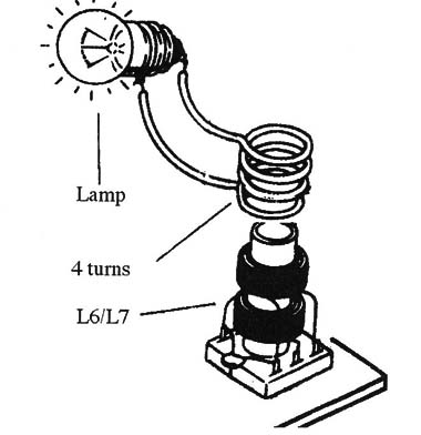
Place any FM receiver near the transmitter, and tune it to a free point inthe FM band. Power the transmitter up and adjust CV1 to tune the signal in the receiver.
A program source, such as a tape recorder or CD player, can be plugged into the transmitter.
The next step is adjust CV2 and CV3 to the highest output power. The lamp in the Hertz loop will glow with the highest brightness when the ideal point is found.
Readjust CV1 to set the tuned signal to the exact desired frequency.
Use only a plastic or wooden tool to adjust the trimmers; metal tools can alter the capacitance by their presence, making these adjustments difficult.
After adjustment, the circuit can be used with an appropriate sound source.
When using an external antenna, also adjust CV4 for best performance.
For this task, you can use a field strength meter. (See in other projects in thios section to learn how a multimeter can be used as a field strength meter.)
Power and Range
As discussed occasionally in this section, many people incorrectly believe that
higher transmitter power necessarily results in greater range. In fact, the range of a transmitter depends on factors that include the suitability of the antenna, the presence of obstacles to signal propagation, and many others.
However, talking specifically about FM radios, if the receiver is placed so that there are no obstacles between it and the transmitting antenna, it is correct to say that more output power produces greater range.
And, by a simple propagation rule, we can say that to double the range, we must quadruple the output power.
This is because the amount of energy that reaches the receiver antenna is reduced by a factor of the square of the distance. It is important to consider those factors when designing a powerful transmitter, because the distance gained may not be worth the money it takes to build it.
Semiconductors
Q1, Q2 - 2N2218 or equivalent silicon NPN RF transistors (see text)
Q3, Q4 - 2N3866 NPN RF silicon power transistors
D1 - BB809 or BB909 variable capacitance diode (varicap) or equivalent (see text)
Resistors (1/8 W, 5%)
R1 - 6,800 ohm - blue, gray, red
R2 - 4,700 ohm - yellow, violet, red
R3 - 47 ohm x 1 W- yellow, violet, black
R4 - 10,000 ohm - brown, black, orange
R5 - 3,900 ohm - orange, White, red
R6 - 22 ohm x 1 W - red, red, black
R7 - 470 ohm - yellow, violet, brown
R8 - 22 ohm x 1 W - red, red, black
P1 - 47,000 ohm trimmer potentiometer
Capacitors
C1 - 0.01 µF ceramic
C2 -10 pF ceramic
C3 - 4.7 or 5.6 pF ceramic
C4 - 120 pF ceramic
C5, C8 - 1,000 pF ceramic
C6 - 0.047 µF ceramic
C7, C9 - 0.1 µF ceramic
C10 - 1,000 µF X 16 WVDC, electrolytic
CV1, CV2, CV3 - trimmers (see text)
Additional Parts and Materials
XRFl, XRF2 -100 µH to 220 µH RF chokes
L1, L3 - 5 turns
L2 - 4 turns*
L4 - 4 turns With a CT
L5 -6 urns with a CT
L6 - 6 turns
J1 - RCA jack or other according to the audio signal source
J2 - coaxial jack to coaxial cable (antenna)
Printed circuit board, metal box, power supply, solder, wires, etc.
All coils are made with AWG 22 Wire in a 0.5 cm of diameter form with ferrite core. L1/L2 and L3/L4 - are wound in the same form.


