Obs. This project is part of my book Electronic Projects From the Next Dimension and originally suggested to perform experiments with EVP (see more in our paranormal electronics section).

The circuit produces a white/pink noise channel to be received by a common FM receiver. Placed near the receiver, its signal is strong enough to be tuned without any difficulty, even in regions with a congested FM band.
As explained before, many researchers believe that the noise in the electromagnetic band can be used more efficiently by the “beings” when producing their voices or other signals to be revealed to us.
The circuit shown has its own noise generator included, but any transmitter can be used with any of our noise generators in these experiments.
How It Works
The modulation circuit is one of our white noise generators that use transistors.
You can alter the project using other white noise generators as modulators.
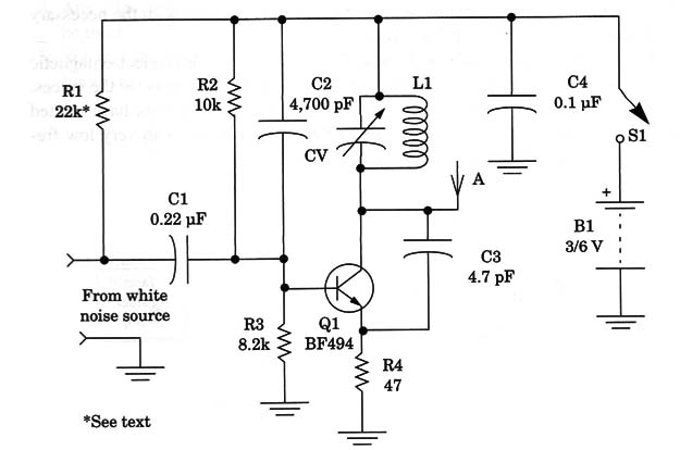
The signal produced by this circuit is applied to a one-stage, low-power, high-frequency oscillator using a bipolar transistor. The output power of this stage is a few milliwatts, which can transmit the signals a distance of up to 20 m.
This low power is important to avoid problems with the FCC, but it is high enough to allow us to pick up the signals using common FM receivers placed near the circuit.
If larger antennas (rigid wire with length of 20 cm to 40 cm) are used, the signal can be picked up at distances of up to 50 m.
To tune the signal in the FM band, the coil is formed by four turns of 22 to 26 AWG wire in a coreless form with a diameter of 1 cm.
The antenna is a piece of rigid wire 10 to 20 cm long. The signals can be tuned to an unused portion of the FM band.
Background noise also can be used to pick up images if a TV set is used as the receiver. A videocassette recorder can be used to register the images in a tape.
The snowy image in a TV is produced when weak signals are tuned in and the noise overlaps them, or when the TV is tuned between channels, in which case the snow is caused by noise picked up by the antenna (atmospheric noise) and also generated by the electrical circuits.
Antique analog TV receivers are recommended for these experiments, as many new models have “squelch” circuits that cut off the signals when only noise is detected at the input.
Many researchers have recorded frames of snowy images that seem to contain no data but, when processed, can reveal shadows of persons and images of strange places or unknown beings. Several accessories can be used to separate the noise from the information, including electronic filters in the video recorder circuit or in the TV, optical filters, and signal processing circuits.
It is important for the reader to understand that the researchers are trying to extract useful information from what we pick up as noise.
We can draw a parallel with a situation in which a civilization has discovered radio but not how to separate the stations from one another. In such a case, the radio would pick up signals from many unknown stations, which would be mixed together and with background noise.
The great problem we have and are trying to solve is how to precisely tune to the desired signals, separating them from the noise and other undesirable signals.
And, most importantly, we need to determine their origin.
The circuit shown in Fig. 1 can also be used to send a signal to a TV tuned be tween channels 2 and 5 (VHF Band), producing a snow pattern that can be recorded for research.
Assembly
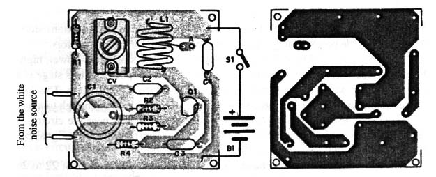
The white noise transmitter can be mounted on a small printed circuit board as shown in Fig. 2.

The white noise generator is mounted on a separate circuit board.
Any trimmer capacitor with a maximum capacitance ranging from 20 to 50 pF can be used. This component is used to tune the transmitter to a free point in the FM band or an unused TV channel between 2 and 6.
The circuit is powered from 6 AA cells or a 9 V battery. Don’t use any other type of capacitors where the parts list recommends ceramic ones.
Using the Circuit
Place the transmitter near the receiver. Tune the FM receiver to a free point in the hand. Then, turn on S1 in the transmitter and adjust the trimmer until it picks up the strongest signal.
If your FM receiver system includes a tape recorder, you only have to record the signals and process them afterward. If not, you can place a tape recorder near the loudspeaker that produces the sounds.
Resistor R1 can be removed, in some cases. Conduct experiments to find the best value for this component (in the range of 22 k ohm to 1 M ohm.
In places where there are too many stations operating in the FM band, it can be difficult to find an unused frequency point to perform the experiments. In this case, you can reduce the size of the receiver’s antenna so it cannot pick up signals from weak stations and place the transmitter closer to the radio.
Suggestions
- You can change the frequency of the transmitter by altering L1. Using 11 turns in the coil and replacing C3 with a 22 to 47 pF ceramic capacitor, you can tune to the signals of a CB receiver or transceiver.
- Use this circuit to transmit the signals to a receiver that will fill an ambient with white noise. Then use a microphone plugged into a tape recorder to pick up the ambient noise produced by the receiver. The voices then can be revealed.
Transmitter
Q1- BC494 or 2N2222, RF silicon NPN transistor
Resistors
R1 - 22 k ohm to 1 M ohm (see text)
R2 - 10 k ohm, 1/8 W, 5% - brown, black, orange
R3 - 8.2 k ohm. 1/8 W, 5% - gray, red. red
R4 - 47 ohm, 1/8 W, 5% - yellow, Violet, black
Capacitors
C1 – 0.22 u1F, ceramic or metal film
C2 - 4,700 pF, ceramic
C3 -4.7 pF. ceramic
C4 - 0.1 µF, ceramic
CV - 2 to 20 pF, trimmer capacitor (or any other)
Miscellaneous
L1 - Coil (see text)
S1 -SPST, toggle or slide switch
B1 - 3 or 6 V, two or four AA cells
A - Antenna, see text
Printed circuit board, cell holder, plastic box. wires, etc.


