Obs. Since the original text was included in my book Electronic Projects from the Next Dimension (Newnes 2001), it describes mainly experiments in paranomal phenomenon involving images. See more in the Paranormal section in this site.
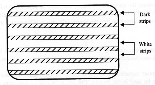
The circuit described here produces a horizontal bar pattern, filling the TV screen, and can be used for dynamic effects when recorded from a camera due to the beat effect of the scanning frequencies of the two devices (TV and camera).
Figure 1 shows the image generated by this circuit on a TV screen.

This circuit includes the low-frequency oscillator suggested in the previous project to produce the horizontal bars in a TV screen.
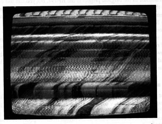
The experimenter can adjust the horizontal synchronization of the TV receiver to obtain a pattern like the one shown in Fig. 2.

With the aid of optical filters, the received images can be processed to reveal some interesting things.
How It Works
Our circuit is formed by a single low-frequency generator that applies the signal to a video carrier. The circuit is tuned to a free channel in the VHF TV band.
When picked up by the TV, the video circuits see the low-frequency component of the signal as image signals, converting them into horizontal dark and clear lines according to the logic level.
The number of lines and their width depend on the low-frequency oscillator and the duty cycle of the signal. These values can be adjusted by two controls: P1 and P2 simultaneously control the duty cycle and therefore the width of the dark and clear lines that appear on the TV screen.
Of course, the lines are not in color but, for this experiment, they are suitable.
The low-frequency circuit is made with one of the four NAND gates of a 4093 CMOS IC.
The other three gates are used as a digital amplifier, buffering the signal to a high-frequency stage using a transistor. The high-frequency stage of the circuit is a low-power transmitter that sends the signals to a TV placed up to 10 m away.
Therefore, no physical connection is needed between them.
CV determines the operation frequency and must be adjusted to a free channel in the low VHF TV band, between channels 2 and 6. L can be altered as in the previous project to transmit into the upper VHF channels between 7 and 13.
Assembly
The complete schematic diagram of the Horizontal Bar Generator is shown in Fig. 1

The components can be placed on a small printed circuit board as shown by Fig. 2.

Any trimmer capacitor with capacitance in the range between 1-15 and 3-30 pF can be used in the project. The coil is formed by four turns of 20 to 24 AWG wire with a diameter of 1 cm without core (air core).
The transistor in the original project is the BF494, but you can use equivalents such as the 2N2222, 2N 2218, etc. You only have to take care with the terminal placement. The 2N2222, for instance, has a terminal placement different from the original BF494.
Without an antenna, the circuit can send the signals distances up to 10 m, but you can use a small antenna to extend this range to up to 30 m. The antenna is a piece of rigid wire 10 to 30 cm long connected to the collector of transistor Q1.
To power the circuit, two or four AA cells can be used. The current drain is not high, and the cells’ life can extend to several weeks in normal use. All the components can be fit into a plastic box, making the unit portable and easy to use.
Testing and Using the Circuit
Place the circuit near a TV tuned to a free channel between 2 and 6. Turn on the power supply and adjust CV until the signal from the bar generator is picked up.
Adjust P1 and P2 to get the desired bar pattern on the screen.
The sound must be at minimum, as the signal from the generator is reproduced by the TV loudspeaker as a continuous tone. Experiments can be made with the bar pattern on the screen, but you can add some “effects.”
Adjusting the horizontal synchronization control, you can bend the picture and get a random pattern as shown before.
Suggestions
If the circuit is placed too far from the TV, the signal will not be strong enough to cover the natural noise. Therefore, you will have an image composed of only the horizontal lines and the snowy image of a free channel. Be sure to not use a channel that includes signals from distant stations that can mix with your signal, allowing the weak images to affect the experiment.
Vary C1 in the range between 1 nF and 220 nF to change the line pattern.
Place a mixer between C2 and the transmitter stage. Apply the signal of any white noise source to the other input of the mixer. You can work simultaneously with the bar pattern and the noise pattern generated by the two circuits.
Replace the transistor with a µHF type such as the BF689K or BF967 (Phillips), reduce C4 to 1.0 to 2.2 pF, and reduce the coil to one turn with the same diameter, and the circuit will produce signals in the µHF low band (channels from 14 to 40).
A modulation control can be added between C2 and the input of a transmitter. Replace R4 with a 10 k9 potentiometer and Wire C2 to its cursor.
Semiconductors
IC1 - 4093 CMOS integrated circuit
Q1 - BF494, 2N2218, or 2N2222 NPN high-frequency silicon transistor
D1, D2 - 1N4148 or 1N914, general-purpose silicon diodes
Resistors:
R1, R2 - 10 k ohm, 1/8 W, 5% - brown, black, orange
R3 - 8,200 ohm, 1/8 W, 5% - gray, red, red
R4 - 6,800 ohm, 1/8 W, 5% - blue, gray, red
R5 - 47 ohm, 1/8 W, 5% - yellow, Violet, black
Capacitors
C1 - 0.022 µF, ceramic or metal film
C2 - 0.01 µF, ceramic
C3 - 4,700 pF, ceramic
C4 -10 pF, ceramic
C5 - 0.1 pF, ceramic
CV - Trimmer capacitor (see text)
Miscellaneous
P1, P2 - 100 k ohm- potentiometers
L1 - Coil (see text)
S1 – SPST - toggle or slide switch
B1 - 3 to 6 V, two or four AA cells
PCB, plastic box, antenna (see text), AA cell holder, Wires, solder, etc.


