Features
Power supply voltage: 3 Vdc (or 12 V – see text)
Current drain: 10 to 20 mA (typical)
Frequency range: 88 to 108 MHz
Transmission mode: FM mono
Range: 50 to 100 ft
This transmitter can be installed in a small box (no larger than a cigarette pack) and used to transmit the music from a portable CD player or Walkman (tape player) to an FM receiver in your home or car.
The transmission is monophonic, but the audio has excellent fidelity, as the two channel’s signals are mixed.
When traveling, you can use this device to send music to the car’s more powerful sound system, allowing it to be heard through the loudspeakers rather than headphones or a small built-in speaker.
The circuit can also be used as a very low-power radio station to distribute programs from a tape recorder to a number of FM receivers placed nearby.
The circuit is a low-power device, so the batteries will last a long time.
How It Works
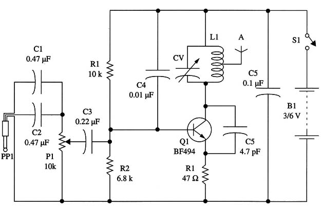
The audio signals coming from the CD player or tape recorder output are mixed by C1 and C2 and applied to a modulation control.
The modulation control is a trimmer potentiometer and is used to fix the level of the modulation signal.
The exact adjustment point for this component is determined by the audio source (CD player or tape recorder) volume. Excessive signals can saturate the circuit, causing overmodulation and severe distortion.
The transmitter is formed by a high-frequency oscillator that uses one transistor.
The frequency is determined by L1 and CV. CV must be adjusted to a free point in the FM band.
The feedback that keeps the oscillator running is provided by C5. R1 and R2 bias the transistor, which is wired in the common base configuration.
This circuit is modulated by the audio signals coming from the audio source.
The high-frequency signal is applied to an antenna for transmission. The antenna is a length of rigid plastic-covered wire 4 to 10 in. long.
Two AA cells form the power supply, for more power, you can use four AA cells without changing the circuit or any component values. If the circuit is intended for use in the car, a step-down converter can be used with the 12 V automotive battery.
A circuit based on the 7806 IC can be used for this task.
Assembly
Figure 1 is a schematic diagram of the CD player/Walkman® transmitter.

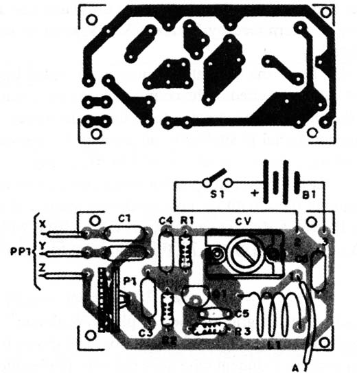
The circuit can be assembled using a printed circuit board as shown in Fig. 2.

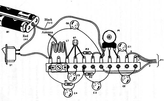
If you are a beginner or a student who does not have the resources to etch your own printed circuit board, you can build the terminal strip version shown in Fig. 3.

This version is more critical, as the component’s terminals and wires must be kept as short as possible. Long wires or terminals can induce the circuit to generate spurious oscillations and instabilities.
L1 is formed with four turns of AWG 18 to 22 enameled or common plastic-covered wire using a pencil as a reference (diameter of about 1 cm).
The antenna can be connected to a tap, with the proper one determined experimentally as described for many other transmitters in this book. The antenna is a piece of rigid plastic-covered wire 4 to 10 in. long.
Any trimmer capacitor with a capacitance range between 2-20 and 4-40 pF can be used. All capacitors are ceramic types.
The reader can change the transistor to a 2N2218 and power the circuit. from a 12 V supply, thereby increasing the output power.
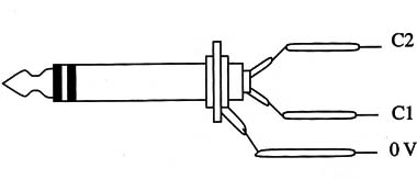
Figure 4 shows how a stereo plug is wired to be used in this circuit.

Keep the wires short, and take care not to allow any wires to touch each other, which can cause shorts that damage the source circuitry.
Adjustments and Use
Place an FM receiver near the transmitter and tune it to a free point in the FM band. Plug a Walkman® or CD player into the transmitter.
The signal is taken from the earphone output using the plug arrangement shown in Fig. 4. The sound source must be adjusted to a low volume point to avoid overmodulating the transmitter, which causes distortion.
Close trimpot P1 and power on the transmitter. Adjust CV to tune the signal to the receiver. Carefully open P1 until the sound from the audio source is heard with best volume and without distortion.
Whenever you use the transmitter for this purpose, the source volume should be the same. This is important to avoid having to readjust P1.
If the sound reproduction tends to have too much treble, increase the values of C1 and C2. When using the transmitter in the car, position the antenna for the best reception without interference or noise.
Semiconductors
Q1 - BF494 or equivalent high-frequency NPN silicon transistor
Resistors (l/8W, 5%)
R1 - 10,000 Ω - brown, black, orange
R1 - 6,800 Ω - blue, gray, red
R3 - 47 ohm - yellow, violet, black
P1 - 10,000 ohm - trimmer potentiometer
Capacitors
C1, C2, C6 - 0.1 µF- ceramic
C3 - 0.22 µF- ceramic or metal film
C4 - 0.01 µF - ceramic
C5 - 4.7 pF - ceramic
CV - trimmer (see text)
Additional Parts and Materials
S1 - SPST toggle or slide switch
B1 - 3 V, two AA cells (see text)
PP1 - stereo plug according to the signal source (earphone output)
L1 - coil (see text)
Printed circuit board, battery holder, plastic box, antenna, wires, solder, etc.


