This circuit is useful for the detection of a falling object, the opening or closing of a door, the passage of a human body, and similar events.
Features
Power supply: 6 Vdc (four AA cells)
Range: 150 ft (basic version)
Frequency range: 88 to 108 MHz
Sensors: LDR for the basic version
How can we monitor a door without being there? How can we detect remote phenomena in scientific experiments without using wires? The solution is this event monitor/transmitter. The device sends out a signal whenever something triggers a sensor.
Our basic version uses a light sensor (photoresistor, also known as a light-dependent resistor or LDR) to detect the presence of objects or persons when they interrupt a light beam or change the amount of light falling onto the sensor.
For example, by placing a tube filled with a chemical solution between the sensor and a light source, it is possible to detect when the solution inside the tube changes from transparent to cloudy. In this way, we can monitor chemical processes from a distance, with no physical connection between the monitor and FM transmitter.
Other interesting applications for this project are as follows:
A secret agent, detective, or spy can use the circuit to detect an intruder.
A scientific researcher can follow experiments at a distance without leaving the laboratory.
Via a remote receiver, a shopkeeper can detect when a customer enters the shop.
How It Works
A block diagram that illustrates the operating principle of this project is shown in Fig. 1.
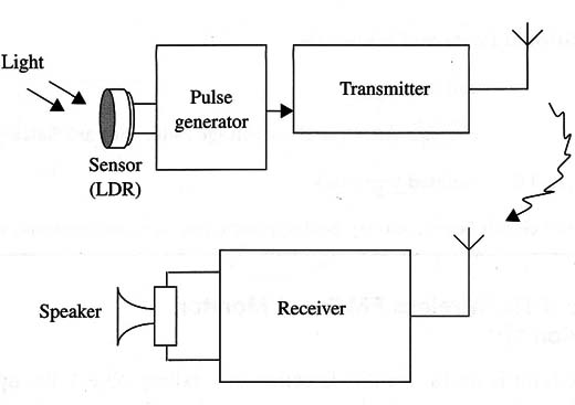
The circuit is formed by a transmitter that is modulated by spaced “beeps.” The beeps are generated by a low-frequency oscillator using the 555 integrated circuit.
The separation between the beeps is controlled by the sensor. Therefore, if the amount of light falling onto the sensor changes, so does the beep rate.
The recommended sensor is an LDR or photoresistor, a device whose electrical resistance depends on the amount of light falling on a sensitive surface. In the dark, the device has a very high electrical resistance-in the range of several megΩ. When exposed to light, the resistance falls to several hundred Ω or less.
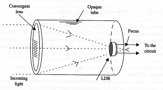
This sensor can be mounted inside an opaque tube with a convergent lens placed in front of it. In this way, it is possible to increase its sensitivity and directivity as shown in Fig. 2.
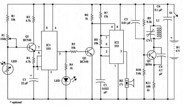
The LDR is wired to the base of a transistor that controls the frequency produced by an astable 555. In the 555 oscillator, the frequency is governed by C1, resistors R2 and R3, and the resistance between the emitter and collector of Q1, depending on the amount of light that falls onto the sensor. Therefore, a change in the amount of light also changes the time constant in the oscillator circuit and thereby the frequency.
The trimmer potentiometer is used to adjust the central frequency produced by the oscillator as appropriate for the amount of light used to control the circuit.
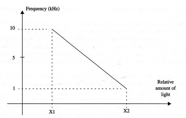
In normal operation, the circuit is adjusted to produce pulses separated by wide time intervals. But, at the instant in which a person passes in front of the sensor and thereby reduces the amount of light falling onto it, the frequency increases, shortening the interval between the beeps.
Figure 3 graphically illustrates how the beeps change in frequency rate by a ratio of about 10:1.
An LED wired to the output of the oscillator acts as a monitor. After this point in the circuit, the pulse is inverted and used to control an audio oscillator that uses another 555 IC, as shown in Fig. 4.
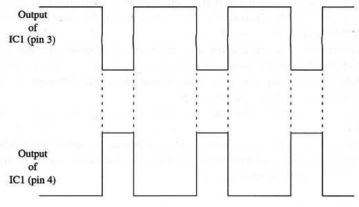
The beep frequency is established by R7, R8, and C2. The reader can change these components to alter the tone (C2 in particular, between 10 and 100 µF).
The separated bits can be picked up from the circuit output (IC2, pin 3) to be applied to the high-frequency stage. The high-frequency output stage, which acts as a transmitter, is formed using a BF494 in the same configuration as for many other projects described in this book.
The frequency is determined by L1 and CV. CV must be adjusted to a free point in the FM band.
If the reader requires more power in this stage, other circuits can be used. Elsewhere in this book, the reader can find transmitter circuits that can send signals over distances up to several miles. The simplest modification to increase the power is to replace transistor Q3 with a 2N2218 and the power supply by 9 or 12 V batteries.
Assembly
The circuit diagram for the Event Transmitter is shown in Fig. 5.
The components are placed on a universal printed circuit board as shown in Fig. 6.

Notice that this configuration can be used to test the circuit on a solderless board. Because this is a high-frequency circuit, it is important to keep all connections as short as possible.
Any LDR can be used in this circuit, as can other resistive sensors such as NTCs or PTCs. You can find an LDR in any old TV set that contains an automatic brightness control. The LDR can be wired to the circuit via a long cable.
Placing the LDR at a distance from the transmitter allows optimal transmitter placement for the best transmission characteristics.
The trimmer capacitor can range from 2-20 to 4-40 pF, and any type, porcelain or plastic, can be used. The coil is formed by four turns of AWG 18 to 22 enameled or plastic-covered rigid wire on a 1 cm dia. form. Use a pencil as reference for winding the coil. You can alter this coil to transmit signals in other bands.
With six or seven turns, it is possible to transmit signals in the low VHF band between 40 and 70 MHz. The antenna can be a piece of plastic-covered rigid wire 10 to 30 in. long or a telescoping antenna.
Adjustment and Use
Place near the transmitter any FM receiver tuned to a free point of the FM band.
Power on the transmitter and adjust CV to tune the signal. A series of beeps will be reproduced by the receiver’s loudspeaker.
Adjust P1 to change the beep rate. When you pass your hand in front of the sensor (LDR), the beep rate should change. Experiment to find the correct P1 adjustment for the application you have in mind. If necessary, install the LDR in an opaque tube with a lens to increase sensitivity.
To use the device, aim the sensor to pick up light changes caused by the event to be detected. Tune the receiver and pay attention to frequency changes. Any frequency change means that something happened to change the amount of light falling onto the LDR.
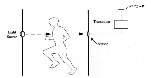
Figure 7 shows the circuit used to detect when someone enters a room. The light source is not always necessary; under some circumstances, ambient light may be sufficient to act on the sensor.
How to Make a Small-Capacitance Capacitor
If you have trouble finding the small capacitor C5, a home-made replacement can be fabricated. This is not a critical component, and values between 2.2 and 5 pF normally can be used in these projects. It is not necessary to match the exact dimensions of the commercial parts. Figure 8 shows how such a capacitor can be made using interwoven, plastic-covered, rigid wires.

Other Sensors
Temperature changes can be detected using sensors such as negative temperature coefficient (NTC) or positive temperature coefficient (PTC) resistors. The resistance of these devices changes with temperature. The ideal device to be used in this circuit must have a resistance between 10,000 and 100,000 ohm at ambient temperatures. A transducer can be wired into the circuit for self-monitoring as shown in the schematic diagram.
Semiconductors
IC1, IC2 - 555 integrated circuits, timer
Q1, Q2 - BC548 or equivalent general purpose NPN silicon transistors
Q3 - BF494 or 2N2218 high-frequency NPN silicon transistor (see text)
LED1 - common red LED
Resistors (1/8 W, 5%)
R1, R5, R8 - 10,000 ohm-brown, black, orange
R2, R3 - 4,700 ohm-yellow, violet, red
R4, R6 - 1,000 ohm-brown, black, red
R7 - 15,000 ohm-brown, green, orange
R8 - 8,200 ohm-gray, red, red
R10 - 5,600 ohm-green, blue, red
R11 - 100 ohm-brown, black, brown
P1 - 100,000 ohm-trimmer or common potentiometer (linear or log)
Capacitors
C1- 22 µF/ 12 WVDC, electrolytic
C2, C4 - 0.022 µF, ceramic or metal film
C3 - 0,01 µF, ceramic
C5 - 5.6 or 4,7 pF, ceramic
C6 - 0.1 µF, ceramic
CV - trimmer capacitor (see text)
Additional Parts and Materials
LDR - Any light dependent resistor (LDR), photoresistor, or CdS cell (see text)
BZ - piezoelectric transducer (see text)
L1 - coil (see text)
S1 - SPST toggle or slide switch
B1 - 6 V, four AA cells or 12 V supply When using the 2N2218 (see text)
Printed circuit board, battery holder, plastic box, hardware for the LDR (tube, lens, etc.), Wires, solder, etc.


