The basic capacitors are devices formed by a piece of insulating material between two pieces of conductive material.
When DC voltage is applied to the capacitor, the electricity carried by the electric charge is stored up to each electrode.
The capacitor energy lies in the electrical field formed between the pieces of metal or electrodes called plates.
The insulator material is also referred to as dielectric.
In electronic equipment, capacitors are used in many important functions.
They can be found in many formats, sizes, and with different dielectric materials.
The name of a capacitor is given by the material used as the dielectric. For example, a capacitor that uses ceramic as its dielectric is a ceramic capacitor, and a capacitor using mica as its dielectric is a mica capacitor.
Symbols and Types
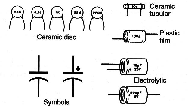
The types of commonly used capacitors and the symbols used to represent them are shown in Figure 1.

Some differences in representations are also found between diagrams as the European symbol used to represent capacitors is different than the American.
About the types, notice the differences in the manufacturing processes that result in tubular types (where the metal plates and dielectric form a coil) and the plate (where the dielectric is a planar piece).
The differences in types are very important as each capacitor has specific applications according to some electric properties of the material used and the format.
For example, ceramic capacitors are suitable for high-frequency applications although polyester film is not.
The plastic film capacitors such as polyester and polypropylene are used in low and medium frequency applications.
It is also important to know that electrolytic capacitors are polarized components. This means that they have definite positive and negative electrodes or plates.
They can’t be inverted when used in a circuit because this can cause the breakdown of the material used as dielectric conductor. In some cases, if a large current flows through the component during a fail, an explosion can occur.
Specifications
The reader, when replacing a capacitor, must be aware of these specifications:
a). Capacitance
Capacitance is measured in farads. In normal applications the capacitances are very small when compared to this unit. So, the capacitances are expressed in multiples such as microfarads, nanofarads, and picofarads.
Table 1 gives the conversion factor, the symbol, and the value of these units.

As in a resistor, some capacitors are too small to have the value printed on them.
Some codes are used to express the capacitance of a capacitor.
One of these is the “three-digit code.” This code is formed by three numbers, or two numbers and a letter.
If two numbers and a letter are used, it is easy to read the value as shown by these examples:
10n = 10 nF
47p = 47 pF
3.3n = 3.3 nF
If three numbers are used, the first two digits show the first and second figures of the capacitance and the third becomes a multiplier which determines how many zeros are to be added to the capacity as in these examples.
102 =10 00 = 1000 pF
473 = 47 000 = 47 ka or 47 nF (k = 1000)
Under 100 pF only two digits are displayed: 27 is 27 pF.
Figure 1, where many types of capacitors are shown, gives some samples with this kind of value indication.
Working Voltage
The capacitance of a capacitor depends on the distance between plates and the nature of the material used as a dielectric.
The thicker the insulator in a capacitor, the greater its volume, but the smaller its capacitance. Otherwise, if the insulator is very thin, it can’t isolate high voltages.
Also, the physical construction of a capacitor is important to indicate the highest voltage that can be applied between plates. This is the maximum operating voltage, sometimes expressed as a WVDC (Working Voltage DC).
Types with working voltages in the range from very low voltages to more than 1kV are found in electronic equipment.
Type
The principal types of capacitors found in electronic circuits are:
Electrolytic capacitors (Electrochemical type)
This type of capacitor uses aluminum as the electrode and a thin oxidization membrane as the dielectric.
This layer is so thin that high capacitances can be achieved. But, since the layer is formed in an electrolytic process (thus the name), they are polarized.
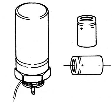
The pole is identified by a mark in the component (see Figure 2). Electrolytic capacitors have a pole indication that must be observed when installing them.

Electrolytic capacitors are found in a capacitance range from 1 UP to more than 220,000 µF and are used in DC and low-frequency circuits.
Tantalum capacitors
This is a special type of electrolytic capacitor using the material called tantalum for the electrode.
Since tantalum oxide has greater dielectric constant when compared with aluminum, tantalum capacitors can be made with very large capacitances and small sizes.
Even this capacitor there is polarity. It usually uses the symbol (+) to show the positive lead. Tantalum capacitors are found in a range of values starting from 0.1 µF.
Ceramic capacitors
Special ceramics, such as titanium acid barium, are used as a dielectric in this kind of capacitor.
The electric properties of the dielectric make this capacitor useful in high-frequency applications.
The most common type is the disk style.
The capacitance of ceramic capacitors is comparatively small. They are typically found in values between 1 pF and 470 nF.
Polystyrene film capacitor
This capacitor is included in the family of the plastic film capacitors. A thin film of polystyrene is used as a dielectric in this capacitor.
Since the plates and the dielectric form thin foils that are wound in a coil, the component presents some inductance.
Because of this factor, this capacitor is not recommended for use in high-frequency circuits.
Polyester film capacitor
Another type of plastic film capacitor is the polyester film capacitor.
This kind of capacitor is recommended for high-frequency applications and can be found in a range from very low picofarads to 10 UP or more.
Other capacitors
Other capacitors in this component family are polypropylene capacitors used in applications where low tolerances are needed, mica capacitors used in applications where high stability is needed, and metalized polyester film capacitors used in miniaturization applications.
In antique equipment other types such as oil/paper capacitors can be found.
These capacitors use a paper infused in oil or dry paper as a dielectric. When restoring a piece of antique equipment where a damaged oil or paper capacitor is found, it can be replaced by an equivalent plastic film capacitor.
Where they are found
The reader is familiar with capacitors since they are used with motors and in other electrical applications.
However, the capacitors found in electronic equipment are found in a much larger assortment of types, values, and sizes as well as in every part.
Capacitors have special electric properties that make them very important to the performance of all electronic circuits.
They can be used to measure time intervals, to perform calculus in computers, and to separate AC signals from DC signals in audio and high-frequency circuits.
They are also used as filters and for energy storage in many applications.
Testing
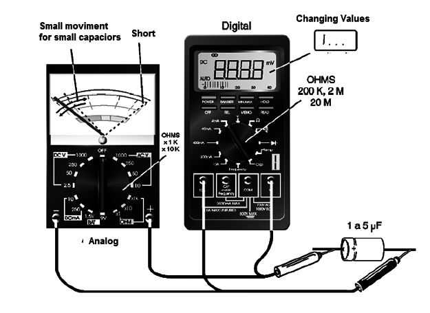
When connecting the probes of an analog meter to the terminal of an electrolytic capacitor (10 µF or greater) a current flow is registered by the needle’s movement.

This current flows while the electric charge is storing up. The current stops flowing when the charge finishes storing.
The oscillating movement of a needle in a multimeter can be used to test an electrolytic capacitor. Use an intermediate resistance scale for this task.
Once charged, capacitors are like open circuits. When perfect, they can’t let the current pass through them.
This means that good capacitors have a very high resistance that can be measured with the aid of any common analog or digital multimeter. if a capacitor presents low resistances (under a hundred thousand Ω) we say that it presents losses or is shorted and must be replaced.


