With over 1 billion units sold by month, the integrated circuit 555 is probably the most important component of this family, from all that were launched in the world. CMOS versions and low voltage of this component are exceptional when it is desired timing up to 1 hour or generating constant duration pulses, or even in applications that need to be generated rectangular signals up to 500 kHz.
THE INTEGRATED CIRCUIT 555
The integrated circuit 555 consists of a general purpose timer which can operate as both astable and monostable configuration. The basic IC pinout is shown in figure 1.
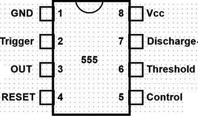
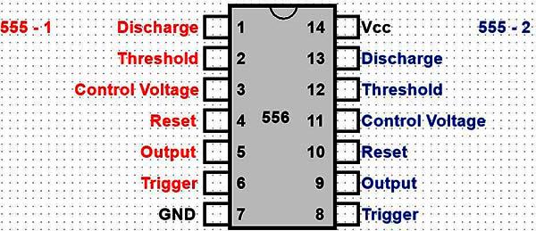
Although there is an old version with a 14-pin case, it is hard to be found nowadays. An important version of the 555 is the double 555, known as 556, whose pinout can be seen in figure 2.
In practice, manufacturers add prefixes to identify their 555, and denominations like LM555, NE555, ?A555 and others are common. We also have different versions for the 555 which use more advanced technologies than the linear traditional.
Thus, the first to be highlighted is CMOS 555 also specified as TL7555 or TLC7555, which is characterized by operating in lower voltages than the common 555, having lower power consumption and achieving higher frequencies. In figure 3 we have a simplified diagram of the functions there are in the integrated circuit 555.
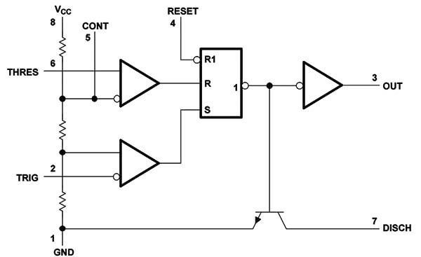
These blocks can be used in two basic ways (that will be analyzed thoroughly), which are astable (free running) and monostable (one pulse). In the astable version, the circuit operates as an oscillator generating rectangular signals available on pin 3 output. In the monostable version, the circuit generates a single rectangular pulse to be triggered externally. The main characteristics of the 555 are:
Characteristics: (*)
| Supply voltage range | 4.5 - 18 V |
| Maximum output current | +/- 200 mA |
| Typical threshold voltage at 5V power | 3.3 V |
| Typical threshold current | 30 nA |
| Typical trigger level at 5V power | 1.67 V |
| Typical reset voltage | 0.7 V |
| Maximum dissipation | 500 mW |
| Typical supply current at 5V | 3 mA |
| Typical supply current at 15V | 10 mA |
| Typical output voltage at high level with 5 V power ( Io = 50 mA ) | 3.3 V |
| Typical output voltage at low level with 5 V power (Io = 8 mA) | 0.1 V |
( * ) The characteristics of this table are given for the NE555 from Texas Instruments and it may slightly vary for ICs from other manufacturers or with eventual suffixes indicating special lines.
SETTINGS
The integrated circuit 555 can be used in two basic configurations, astable and monostable, we analyzed below:
a) Astable
In figure 4 we have the basic circuit 555 in astable configuration.
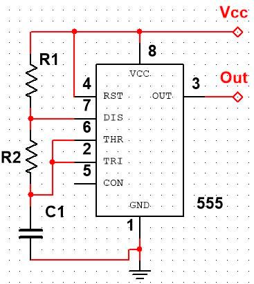
This circuit can generate signals from 0.01 Hz to 500 kHz, and the limit values for the used components are:
The frequency of oscillation is given by:
f = 1,44 /[(R1 + 2R2) C]
Where:
f is the frequency in hertz
R1 and R2 are the resistor values in Ω
C is the capacitance in farads.
The time in which the output remains at the high level is given by:
th = 0,693 x C (R1 + R2)
The time in which the output remains at the low level is given by:
tl = 0,693 x R2 x C
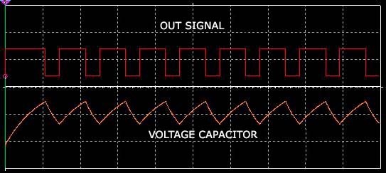
Note that, in this configuration, the active cycle can’t be 50% in any case, because the capacitor charging time is always greater than the discharging time. There are settings in which the paths the currents charge and discharge change to obtain smaller active cycles.
It is also important to observe that the charge and discharge of the capacitor enable obtaining a saw tooth waveform on this component, as shown in figure 5.
Evidently, it is a circuit point which this signal has high impedance and therefore it can’t be used directly to excite higher power loads.
b) Monostable
In monostable configuration, when the trigger input (pin 2) is momentarily taken to the low level, the output (pin 3) goes to the high level for a time interval that depends on R and C values in the circuit of figure 6.
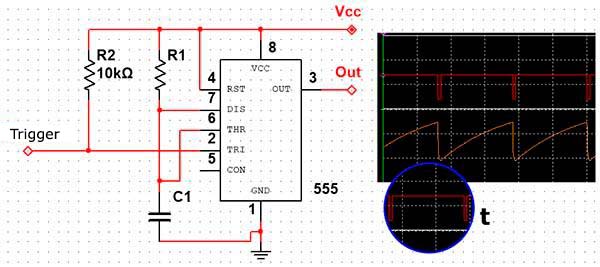
The recommended limits are:
R - 1 k a 3,3 MΩ
C - 500 pF a 2 200 µF
This time can also be calculated by the formula:
Where:
T = 1,1 x R x C
T is the time in seconds
R is the resistance in Ω
C is the capacitance in farads
With the information provided the reader can design their own projects using the 555 from the applications circuits following.
APPLICATIONS
Following we give a number of basic circuits that can be used to generate signals in alarms, to produce audio signals, to provide timers to just over an hour, to detect the absence of pulses and more.
1.Basic Audio Oscillator
In figure 7 we show the circuit of a basic audio oscillator that excites a speaker or transducer.
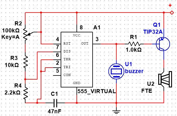
The frequency can be adjusted in a range of 1:10 in the potentiometer and it is basically determined by the value of the capacitor used.
For the excitation of a small piezoelectric transducer of high impedance or a phone capsule, we can directly use the output pin 3. However, for a low impedance load such as a speaker, it should be used an driver transistor. For voltages above 6V the transistor must be built on a heat radiator.
2.Flasher / Metronome
With the use of a capacitor over 1 ?F we have the production of intervaled pulses and the circuit can be used as a metronome, or even excite a lamp in a flasher according to the example of figure 8.
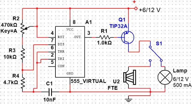
Lamps up to 500 mA can be excited using transistors such as BD136 or TIP32, and to higher powers using appropriate power field-effect transistor.
3. Inverter
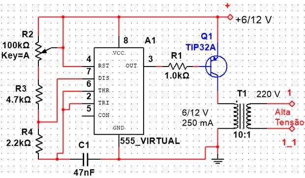
Figure 9 indicates how to connect the 555 to a small high voltage transformer to generate enough voltage to light a small fluorescent lamp, or even make it blink (with the operation in lower frequency). This same circuit can be used to generate stimulus in a nerve exciter.
The transistors can be either bipolar PNP or a power field-effect transistor, it should be provided with a heat radiator, if the feed is over 6 V. The operating frequency is set to P1 and should be chosen according to the transformer characteristics to result in a higher energy transfer performance.
4. Frequency Modulated Oscillator
Pin 5 of the 555 integrated circuit can be used to control the active cycle of the signals in the astable configuration and thereby providing a frequency modulation. In figure 10 we show how to build a basic siren with two integrated circuits 555, where we have the frequency modulation made by the low frequency signal from one of the oscillators.
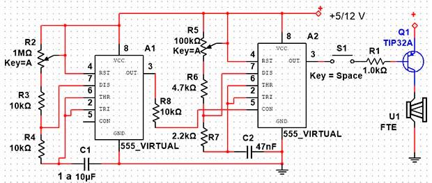
In this circuit, IC1 generates a low frequency signal which is basically determined by the capacitor C1 and by adjusting P1.This signal is applied to modulation pin 5 acting directly on the frequency generated by IC2. In IC2 the frequency is adjusted by P2 and the value of C2. The resistor R3 determines the "depth" of the modulation, in other words, the variation amplitude of the frequency generated by the second oscillator (IC2).
Power steps as observed in the basic oscillator can be used to apply the signal generated by the circuit to a transducer or even a speaker.
5. Oscillator Intermittent
A relay or other charges can be triggered at regular intervals, sound effects and intermittent applications can be obtained from the circuit shown in figure 11.
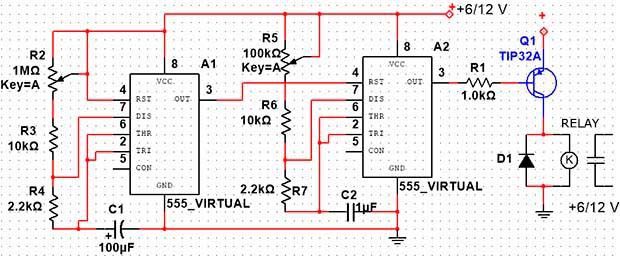
In this circuit, the first oscillator controls the second through its reset pin to turn it on and turn it off in regular intervals. The trigger mode and therefore the frequency of the flicker effect is determined by C1 and adjusted by P1. The example gives typical values of components for triggers that will range from several seconds to over 15 minutes.
The frequency of the second oscillator is set to P1 and basically determined by C2, which also has the typical values, for the audio range shown in the figure. Note that the values from C1 must be much bigger than C2 so that the working cycles of the second oscillator may fit in each of cycle of the first one, as shown in figure 12.
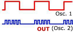
The load depends on the application: simple sound transducers can be used for applications where intermittent audio signals should be generated, even relays or other direct current charges, using the appropriate driver step. An intermittent relay that opens and closes a number of times and then enters standby for a longer time, to have again the same operating cycle, is one possible use for this circuit.
6. Changing the Active Cycle
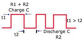
As we have seen at the top, the active cycle of the basic circuit which uses the 555 has the time at the high level given by the sum of the values ??of the two capacitors used and the time at the low level given by the second capacitor.
This makes the time at the top level be always higher than the low level, tending to an active minimum cycle of 50% when R2 has its minimum value and R1 its maximum value, see figure 13.
One way to obtain an active cycle of less than 50% to trigger a load is to work with activation at the low level, what we do when charging is activated by a PNP transistor. However, there is another way to obtain an active cycle lower than 50% without reversing the output signal with a PNP transistor.
This can be accomplished using diodes to provide a separate path for charging and discharging the capacitor, as shown in figure 14.
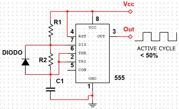
In this circuit, the charge on the capacitor and therefore the time at high level only depends on R1, while the discharge depends only on R2. Thus, instead of formulas for calculating the high level of traditional configuration, we have:
th = 0,693 x R1 x C
tl = 0,693 x R2 x C
For frequency:
f = 1,44/[(R1 + R2) x C]
Where:
f is the frequency in hertz
th is the time at the high level in seconds
tl is the time at the low level in seconds
R1 and R2 are the circuit resistance in Ω
C is the capacitor value in farads.
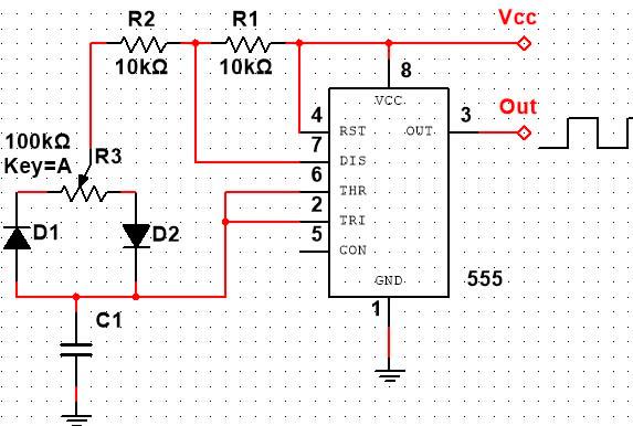
To obtain an adjustable active cycle, we employ either a potentiometer or a trimpot to the configuration shown in figure 15.
7. Simple Timer
In figure 16 we have a basic circuit timer that keeps a relay activated (or other direct current load) for a time interval that can be adjusted from a few seconds to half an hour on the potentiometer P1.
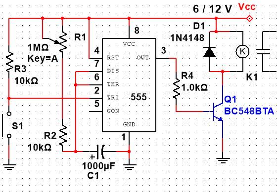
Once the time is adjusted in P1, we press the switch S1 for a moment to bring the output 555 to the high level and thus obtaining the relay trigger or the load in the power transistor collector.
The maximum time that can be obtained by this type of circuit basically depends on the leakage of the electrolytic capacitor C1.
These are leakages that determine its maximum value. When the leakages reach a value formed with P1 a voltage divider which the voltage applied to pin 6 and 7 fall below the trigger point, the circuit does not switch off anymore and remains constantly triggered. It is important that the capacitor placed in this timer has excellent quality so that leakage problems do not affect its operation.
Another problem related to the capacitor is in the residual charge. Once the timer is used the next time it is launched we will not have the same range of time adjusted, because there is always a residual charge on the capacitor from which it starts the time charge. This load significantly affects the accuracy of a timer that uses the 555.
8. Double Timer
In figure 17 we have a very interesting setting for applications in automations of all kinds.
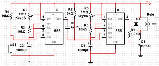
It is the possibility of doing a double timing that when we press S1, the first IC determines the initial time interval, after which the relay used as a load will be triggered. When the relay is triggered, the time interval in which it will be closed will depend on the second IC. Therefore we have an operating curve as seen in figure 18.
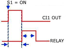
In this curve, t1 is the time interval elapsing between pressing S1 and triggering the relay. t2 is the time the relay is triggered. C1 and C3 values determine t1 and t2 and their limit values are shown in the traditional application. Trimpots in series with these capacitors can be used for time fine adjustments of triggers from each 555 phase. We can go beyond using this idea adding several 555 in series for a sequential trigger, as shown in figure 19.
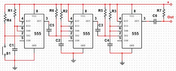
The triggering time sets of each output in a sequence are determined by the capacitors associated with the firing pin and adjusted on trimpots in series with these elements.
9. Photo-Electric Sensor
The integrated circuit 555 can be triggered by grounding by a moment pin 2.
As this pin has a high input impedance, several types of sensors can be used with simple additional circuits to trigger it. One interesting possibility is the trigger by focusing light on a photo-electric sensor that can be used in industrial applications such as a movement alarms, from the presence of objects and much more. The suggested circuit is shown in figure 20.
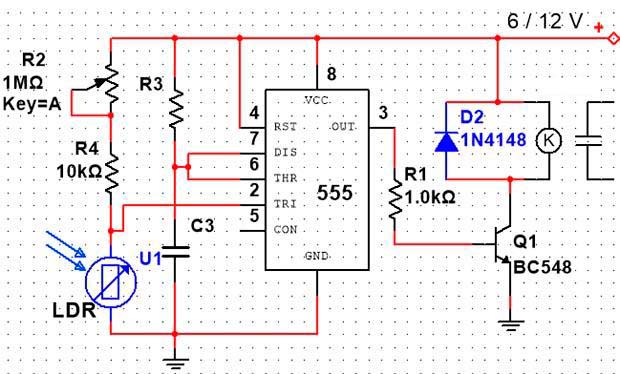
When a beam of light falls on the LDR the transistor conducts and then the trigger 555 input is brought to the low level for a moment, triggering the monostable configuration. The 555 output reaches the high level for a period of time that depends on R and C in the manner we have already seen and which can be calculated by the application on the DC. See that, even after the light pulse applied to the sensor disappears, the relay connected as load remains activated. To start the trigger with a light beam just reversing the sensor connection mode is enough, see figure 21.
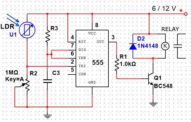
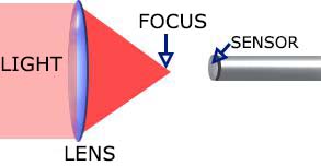
In this circuit, when the light is cut on the LDR for a moment, the transistor conducts putting the low level in the firing pin of the 555 turning on the monostable configuration. In both circuits the sensibility adjustment is made by the trimpot. To achieve higher sensibility and directivity for the activation of the circuit, the sensor must be built into an opaque tube with a converging lens.
Figure 22 shows the sensor position relative to the lens focus to obtain increased sensibility and selectivity.
Color filters can be placed for the selective detection of light in applications requiring more than one operation channel. In these circuits, using larger values trimpots, phototransistors and photodiodes can be used. The sensibility obtained depends on the characteristics of the components used. It is important to note that the phototransistors and photodiodes are much faster than the LDRs in detecting pulses or short duration light cuts.
10. Missing Pulse Detector
An important application of the 555 in automation, data transmission and remote controls is the detector of missing pulses. What this circuit does is to detect when one or more pulses (a sequence that must be kept constant), are missing. In a security system or monitoring a machine operation, the no pulse detector can acknowledge immediately when an interruption occurs in a protective link or even when there is a situation where the control of the pulse train fails.
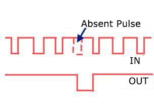
The advantage of the system is the use of pulses at a frequency that enables very large protected areas, or the signal to be sent to a very distant station because it operates by frequency and not by signal strength. In figure 23 we have the basic configuration of the 555 recommended for this application.
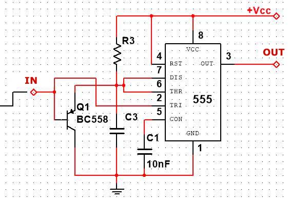
The time constant RC, must be greater than the interval between two transmitted pulses but smaller than two successive intervals (to detect the absence of a pulse). The transmission of the pulses can be made with the aid of another 555 in stable configuration. As the circuit input has high impedance, the distance between the transmitter and the detector can be very large. The waveforms for this implementation are shown in figure 24.
11. Frequency Divider
Another not so much known application for the integrated circuit 555 is as a frequency divider. As we can see in figure 25, the 555 is connected as monostable and the rectangular signal up to 500 kHz whose frequency we want to divide, is applied to the trigger pin 2.
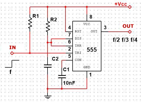
The time constant must then be calculated to have a value corresponding to two, three or four times the input signal period. Under these conditions, taking advantage of the shooting at the end of each timing cycle, we have the input frequency division by these values.
12. Pulse Position Modulation (PPM)
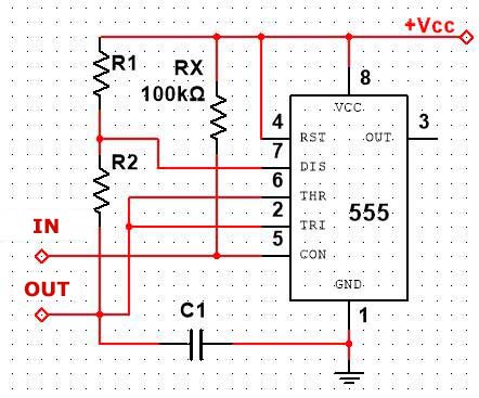
Pulse Position Modulation or PPM is an interesting application for the integrated circuit 555 connected in the astable configuration. Figure 26 shows the circuit. The waveforms obtained by the 555 used in this application are pulses whose separation varies according to the input signal.
CONCLUSION
What we have seen so far is only a small part of what can be done based on the integrated circuit 555 and its versions of lower consumption and voltage.
Working with the active cycle, with the modulation and reset input, the imaginative reader will be able to create applications that would otherwise require dedicated circuits much more expensive and complex. Harnessing the potential of an integrated circuit that can be found easily and at a very low cost can be very important whether in the personal or industrial projects.


