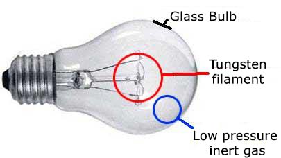
To understand well how a LED works we should compare it to another light source well known as the light bulb. Light bulbs work when a metal filament disposed therein is heated by passing a current. The atoms have their degree of agitation increased so that light emission occurs. So that the metal doesn’t get burned with the atmospheric oxygen, the filament is enclosed in a glass bulb which atmospheric air is either completely removed or replaced by an inert gas mixture, as shown in figure 1.
However, as shown in figure 2, an incandescent lamp is like a untuned radio transmitter, a transmitter of noise. The wave lengths of light that it emits spread all over the spectrum.
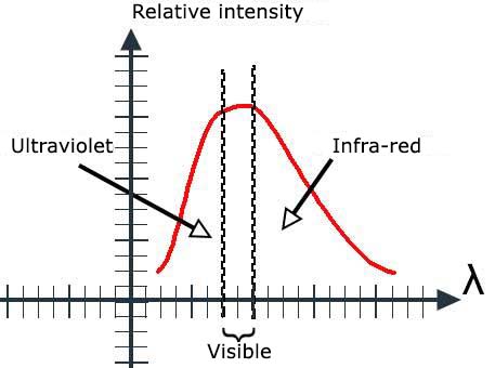
Depending on the voltage applied to the lamp, we have the predominance of certain wavelengths and the emitted light may be yellow, white or tending towards blue. It is therefore not a pure light the one emitted by a standard light bulb.
The LED
LED is short for Light Emitting Diode and its working principle can be understood from the analysis of what happens to the structure of figure 3 when an electric current goes through it.
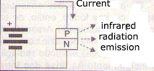
In this structure we have a PN junction, i.e. a common semiconductor diode the readers already know, because it is a widely used component in our projects. When a current passes through the junction the process of recombination of charge carriers causes a stimulus and an emission that is mainly concentrated in the infrared range. An important feature observed in this radiation is that, instead of its frequency to be random, as in the case of the incandescent lamp that spreads the spectrum, it has a frequency very well defined, which depends on the type of material used in the semiconductor, as shown in figure 4.
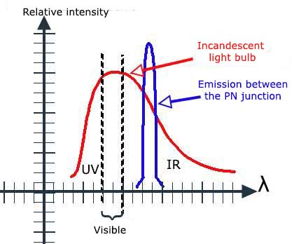
We can say that, unlike an ordinary light bulb, the radiation emitted in this case is "tuned" as it has a single frequency. For ordinary silicon diodes, where it was discovered the phenomenon, the emitted radiation intensity is very small and there is practically no use for it. However, it was also discovered that if other semiconductor materials were used and special dopants were further added it was possible to emit light with higher intensity and in different spectrum ranges.
The first light-emitting diodes created were then of a material called gallium arsenide and gallium arsenide with indium (FgaAs and GaAsI) emitting radiation mainly in the infrared range. The next step was the creation of materials capable of emitting radiation with wavelengths smaller and smaller until they get to the visible spectrum. Then the first LEDs capable of emitting light in the visible spectrum in the red region appeared. In figure 5 we have a common LED with its internal structure.
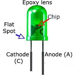
Note that the color of the LED light does not come from plastic that wraps it.
The color of the light depends on the semiconductor material used. If an LED uses red plastic, it is because this plastic has the same color of light emitted and is not it that determines this radiation. LEDs with clear or white plastic can emit light of different colors.
The next step was the development of LEDs that started having colors with increasingly shorter wavelengths within the visible spectrum, as shown in figure 6.
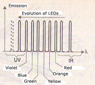
Nowadays It is possible to obtain LEDs capable of emitting blue and even ultraviolet light. One of the main advantages of the LEDs compared to the lamps when they are being used as light sources are their performance. A common LED can have efficiency greater than 80% while there are types of high-yield and high-brightness that go far beyond. A common incandescent lamp, on the other hand, wastes most of the energy applied in the form of heat. Only 20 to 25% of the energy consumed by an incandescent bulb is light. The rest is heat. But it is not only possible to build an emitting tablet in a component. We can set up two tablets, or even more in the same component and thus obtaining two-color LEDs, as shown in figure 7.
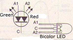
Depending on the tablet which is connected to the circuit the LED glows red or green light. To produce white light or any other color from LEDs there is an interesting possibility based on the same operating principle as color TV.
We know that from the three basic colors, red -R, green -G and blue -B we can get any color by simply dosing the amount of each that enters into the composition. Thus, in a color television image points are formed by triads which are nothing more than points of phosphorus in RGB colors, as shown in figure 8.

If we set up in a single package of three semiconductor LED tablets corresponding to the RGB colors, we can control the current in each one and thus generate light of any color, as shown in figure 9.
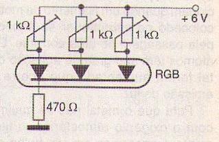
A panel of RGB LEDs can generate color images and this application already exists. The correct combination of the three colors can still result in white light. There are white LEDs which replace ordinary light bulbs, with advantages, in small flashlights and other applications. The low power consumption and higher performance compared to a standard bulb make these LEDs very interesting options for this application.
Electrical Characteristics
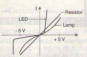
LEDs behave like diodes while incandescent lamps represent non-linear resistive loads. We can compare the characteristic curves of the three devices (lamp, resistor and LED) through the graphic shown in figure 10.
Enlarging the LED characteristics of different colors, we see that the point at which they begin driving can vary its color. Figure 11 shows this.
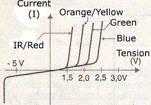
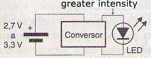
While a germanium diode begins to conduct with 0.2V and a silicon diode with 0.7V, a common red LED needs at least 1.6V to start driving and a blue LED at least 2.7V. In applications that use batteries to power LEDs with higher voltages require special circuits. Thus it is common in mobile phones, and other applications that are powered by batteries from 2.7 to 3.3V, special circuits to be used to increase the voltage in order to excite the LEDs as shown in figure 12.
But when using a LED it is not enough to consider the tension it needs to light. There are other factors to be considered.
One of them is the behavior of the LED which similar to a diode. When the LED starts driving, its resistance drops so that, if there is not a resistor to limit the current it increases to a point that causes it burn itself.
The characteristic curves show this fast increasing of the current with the voltage from the driving point. This means that in practical applications, there must be connected a limiting resistor in series to a LED, as shown in the circuit of Figure 13.
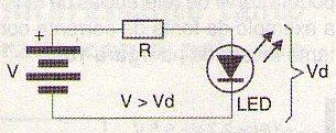
The value of this resistor will depend on the current desire for the LED and the voltage available. The calculation can be done in a simple way using the following formula:
R = (V – Vd)/I
Where:
R is the resistance to be connected in series to the LED (Ω)
V is the DC voltage supply
Vd is the voltage drop on the LED given by the following table
I is the current in the LED
| Color | Vd |
| IInfrared | 1.6 V |
| Red | 1.6 V |
| Orange | 1.8 V |
| Yellow | 1.8 V |
| Green | 2.1 V |
| Blue | 2.7 V |
| White | 2.7 V |
The power resistor dissipation is given by:
P = R x I2
Where:
P is the dissipated power in watts
R is the series resistance in ohms (Ω)
I is the intensity of the current in amperes
As we can see from the characteristic curves, the reverse breakdown voltage of a LED is relatively low, around 5 V for the common types. This means that we must be careful so more than 5 V on reverse direction does not appear in a LED when fed with alternating current. This can be avoided by using a diode in parallel, as shown in figure 14.

We can feed several LEDs in series from a single source with a single resistor. It is not recommended to connect the LEDs in parallel as shown in figure 15.
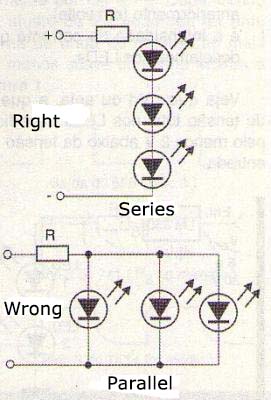
With this connection the current is not equally distributed among the LEDs, as they always have small differences in characteristics. This causes a LED to always shine more than the other. One way is to feed multiple LEDs with the circuit shown in figure 16 wherein they are fed in series.
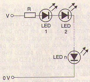
The calculation of the resistor R to be connected in series, will be performed using the following formula:
R = (V – nVd)/I (Para V > nVd + 2 V)
Where
R is the resistor value in Ω
V is the supply voltage
n is the number of connected LED
Vd is the voltage drop in each LED according to the table that we previously showed (in volts)
I is the current intensity that we wish for the LEDs.
See that nVd, i.e. the total voltage drop in the LEDs should be at least 2 V below the input voltage. Another way to feed LEDs efficiently is with the use of a constant current source as shown in figure 17.
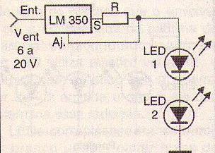
This source current in the LEDs remains constant regardless the input voltage variations. The Rx resistor is calculated by the following formula:
R = 1,25/I
Where:
R is the resistor value in Ω
I is the intensity of the current in the LEDs in amperes
The input voltage in this circuit must be at least 2 V higher than the voltage drop in the LEDs powered. As an active element LEDs can serve as voltage references, such as the constant current source shown in figure 18.
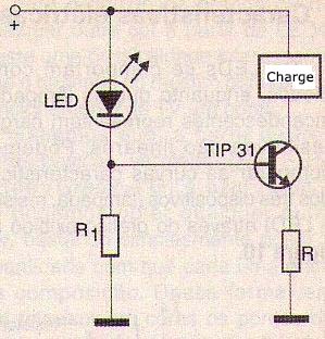
Finally, to feed white or high yield LEDs from a low voltage source LEDs can be used specific integrated circuits as shown in figure 19.
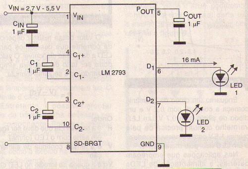
This circuit consists of a voltage doubler that raises the input voltage in the circuit to a value that is more appropriate of the excitation of the LEDs.
Conclusion
The LEDS are presented in infinite applications and their electrical characteristics require special care when fed. Used correctly the LEDs show high performance and an extremely long service life which makes them ideal as a substitute for ordinary light bulbs.


