The basic idea of the radio frequency identification or RFID is to have a very small chip capable of responding to signals from a reading system without needing wires. This chip may be embedded in product tags, bags, luggage, implanted in animals and even in human beings.
There are two technologies for RFID, the one which makes the use of active chips, i.e. the one carrying its own power supply and passive chips that is using its own signal of the remote reading system to power. These chips tend to be the most used nowadays because they either are ease to implement and they are low cost or have unlimited autonomy, as it does not require a battery.
How it works
The basic idea of the active system operation is simple. A chip has a transmitter and a receiver of extremely small dimensions. When the reading transmitter sends a signal requesting the chip information, its receiver gets this signal and activates the transmitter system which answers by sending these information, as shown in Figure 1.
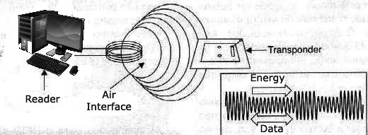
The passive system, on the other hand, operates in a slightly different way which can be understood by the simple circuit of a transformer, as shown in Figure 2.
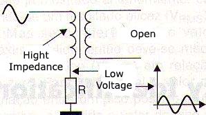
If we apply to the primary winding of this transformer a signal, with the secondary winding open, the signal sees the circuit as a high impedance, i.e. it is not loaded. If we have a resistor in series with the winding, as shown in the same figure, the high impedance of the transformer splits the signal to the resistor and the resistor appears a very low voltage. On the other hand, if the secondary winding of the transformer is short-circuited, as shown in Figure 3, the circuit state changes.
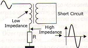
The signal sees the primary winding of the transformer where it is applied as a low impedance, and so the voltage appearing across the resistor is increased. If we go further imagining that the transformer does not have a common core, but is formed by coils separated by a distance, as shown in Figure 4, the effect is the same but the change impedance of the signal sees is smaller, depending on the existing coupling among the coils.
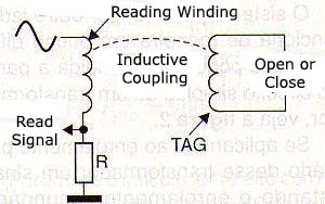
This means that if the primary winding is connected to a reading circuit and the secondary is a coil in a small "tag", we can "read from a distance the logic level 0 or 1 in this tag, depending on the coil to be opened or closed, as shown in Figure 5.
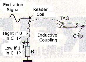
Of course the maximum distance at which this can be done depends on the sensitivity of the reading circuit, but it can have up to one or two meters. It is clear that a single bit for reading does not make it a very practical circuit. The ideal would be if we had the ability to read a few tens or hundreds of bits which can represent some useful information.
This is done just by adding to the small coil a chip and a power system, as shown in Figure 6.
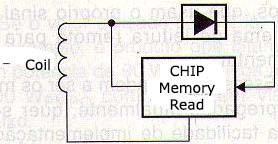
The feed system takes advantage of the induced voltage in the coil when the reading system is approached. The power supply circuit rectifies the signal when its intensity reaches a few volts, feeding the tiny memory chip and its reading.
Evidently, the circuit consumption must be extremely low to not load the coil and thus give the reader a false indication of a high bit. The chip consists of a MOS field-effect transistor matrix and a sequential feeding system according to the simplified diagram shown in Figure 7.
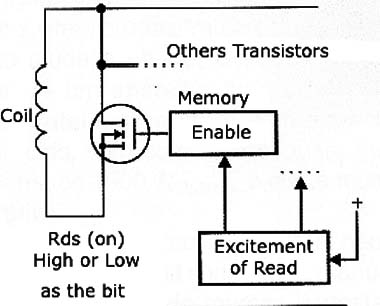
Each CMOS transistor represents a memory unit which can be polarized in order to drive or not as the bit we want to record on it. The reading system turns on each transistor in sequence to the coil so that the data recorded on it is read. So, when a transistor is activated to read the bit recorded on it, which is done by polarizing this transistor there are two possibilities. If the transistor is open, no driving, the coil to be connected to it, reflects a high impedance to the reader circuit which does not see 0 bit. If the transistor is driving, showing a very low resistance, the coil is placed in short and the reading system sees 1 bit.
As the reading is done in sequence, when activated, the reading system gets a bit train that precisely matches the recorded information in the small chip. The chips used in such circuit are extremely small, as shown in Figure 8.
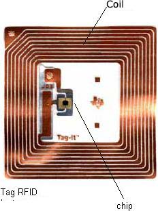
Greater it is the coil that should be used in the system of signal transmission and reception.
Applications
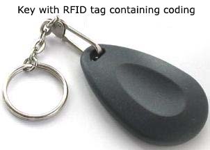
The applications for the RFID are unlimited and what can be recorded on the chip depends only on the size of its memory. We can quote, for example, simple, the modern automobile ignition keys that have the so-called transponder which is nothing more than an embedded RFID tag which contains the activation code of that vehicle, as shown in Figure 9.
Another application is in luggage and goods identification that would have labels with tags which could be read in places where it is necessary. Price information, owner address, etc. would be contained in the chip. We also have the cases of cattles identification, fully used in our days here in our country where a "tag" containing information about the animal would have recorded data as birth date, vaccines, etc.
In people, these tags could be implanted in the handicapped and in people with serious illnesses who would need assistance or help in conditions that they themselves could not provide information. This information would include the address, what to do in the case of need for help, etc.


