The sound waves consist of mechanical vibrations of a natural environment and they spread with a speed that depends on several factors, including the nature of the environment.
Thus, in the air, these are waves of compression and decompression and they propagate under normal conditions at a speed of about 340 meters per second.
Evidently, being mechanical waves, they cannot directly excite the electronic circuits, for this reason there is need to have an intermediate device to make their conversion into electricity.
This device is an electro-acoustic transducer called microphone.

We can say that the microphone works in a "reverse" mode to the speaker: as the speaker receives electrical signals from an amplifier and converts them into sound (acoustic energy), the microphone receives the sound and converts it into electricity.
In order to use a microphone effectively in an electronic device, music recording, voice transmission or an intercom, it must have some well-defined characteristics which are:
a) Fidelity
Fidelity means the microphone's ability to produce an electrical signal that has the same characteristics of the original sounds, ie, intensity, frequency and waveform.
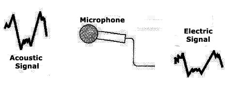
Depending on the type, the microphone can be more sensitive to the sounds of certain frequencies which leads us to a specific use. For example, a microphone sensitive to the sounds of mid-range is appropriate for the transmission of spoken words.
b) Sensitivity
The sensitivity is related to the ability that the microphone has to work with very faint sounds. Depending on the use, we can have more or less sensitive microphones.
c) Directivity
As the construction of the microphone, it can be easier to capture sounds from certain directions. This determines the microphone directivity which can be represented by a graph.
In Figure 3 we give some examples of the directivity graphs.
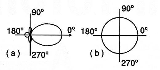
In (a) we have a unidirectional microphone, or a microphone that picks up sounds only from one direction. This type of microphone is often used in studios or in a theater by the presented, where only one person should be heard. In (b) we have an omnidirectional microphone, that is, it has the same sensitivity to sounds from all directions.
TYPES OF MICROPHONES
There are several types of microphones we found in practical applications and which differ as much as the electrical characteristics as well as the operating principle.
Then we have the following types of microphones (some little used nowadays, but whose knowledge is important for historical reasons):
a) Carbon
This undoubtedly is the oldest type, since the first microphones that existed used fine coal grains in a box with a diaphragm, as shown in Figure 4.
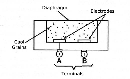
The diaphragm is a metal membrane, plastic or other flexible material which makes direct contact with the coal grains in the box.
The resistance presented by the device, between terminals A and B, depends on the degree of compression of the coal grains.
This way, the sound when reaching the diaphragm moves it so that it starts to compress and stretch the coal grains, thus varying the resistance between points A and B.
The carbon microphone has a low impedance, and as it does not generate electric power, it is necessary to use a circuit with a power source, usually a battery, as shown in Figure 5.
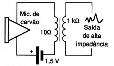
The microphone resistance variation with the incidence of the sound makes the current vary in the primary winding of the transformer. Then it is induced in the secondary of high-impedance of the transformer a signal whose waveform and frequency corresponds to the sound captured.
The carbon microphones are applied in telephony where the human voice must be transmitted, since they have a better response in the medium frequencies.
b) Dynamic microphone
This type of microphone is formed by a coil attached to a diaphragm that moves it in the magnetic field of a permanent magnet, as shown in Figure 6.
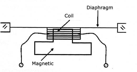
It is practically a working speaker "in reverse". In a common speaker, when the coil is traveled by a current which corresponds to an audio signal, a magnetic field is created and consequently there appears a force that moves the cone back and forth, thereby producing the air compression and decompression waves forming the sound.
If the sound reaches the diaphragm, it moves the assembly including the moving coil in the magnetic field in order to induce a current whose characteristics correspond to this sound.
For this reason small speakers can work as microphones, provided someone speaks in their proximity or that they are pointed to the sound source. However, as they are not manufactured for this purpose, they have some deficiencies when operated as microphones.
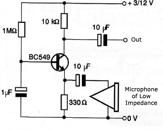
As they are low impedance devices, they must normally be used with a transformer which raises their impedance as the one in Figure 7, or connected to impedance adapter circuits with transistors in common base configuration.
c) Piezoelectric microphones
The ceramic or crystal microphones operate using the advantage of the piezoelectric properties of certain substances such as Rochelle salt, or the ceramics such as barium titanate.
These substances, after suffering mechanical deformations generate proportional electrical voltages.
So, it is enough that a crystal of a substance such as these is coupled to a diaphragm so that the captured sound waves produce mechanical forces that makes the crystal generate electrical signals.
Figure 8 is an example of this type of microphone.
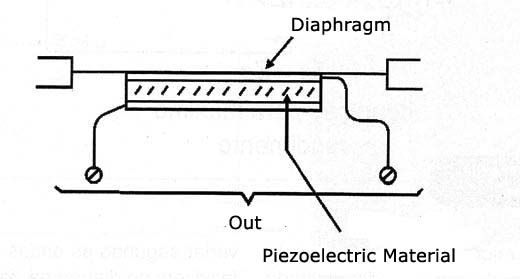
This microphone uses Rochelle salt, and so it is called "the crystal microphone”. Although it is very sensitive, providing relatively strong signals that can directly excite the amplifiers, the crystal microphone is very sensitive to heat and humidity. For this reason nowadays it is almost no longer used, being replaced by ceramic microphones that are more robust and are hardly ever affected by heat and humidity.
d) Electret microphone
There are substances called electrets which have interesting electrical properties.
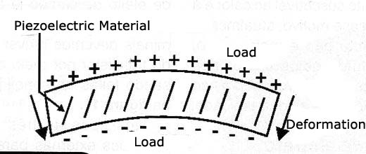
When subjected to a mechanical deformation these substances are charged with static electricity, manifesting proportional voltages between their faces in a manner somewhat similar to the piezoelectric crystals, as shown in Figure 9.
These substances can be molded to form the diaphragms of a microphone and directly connected to a field-effect transistor gate.
This way the current controlled by the transistor will range depending on the sound waves reaching the diaphragm, providing at its output an already amplified signal, as shown in Figure 10.
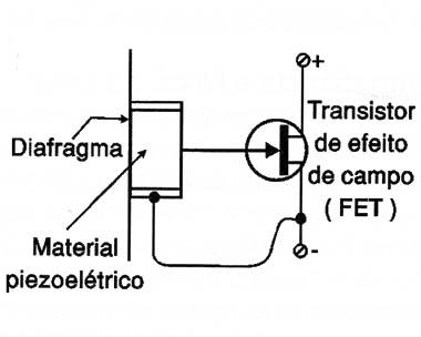
The electret microphones are very sensitive and small, as the field-effect transistor already works as a preamp.
In the types of two terminals we must predict the transistor polarity using a resistor, the connections are made as shown in Figure 11.
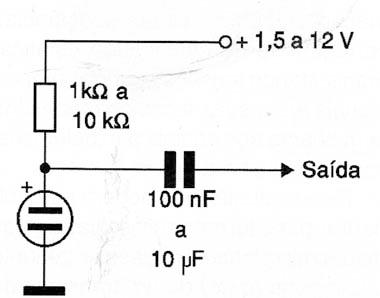
In the types of three terminal the external connections for their use are shown in Figure 12.
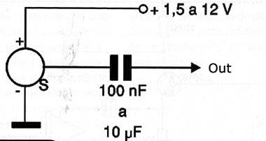
See that for the field-effect transistor to work there must be a source of external power, hence the need of external polarization.
IMPEDANCE AND SIGNAL LEVEL
The microphones have electrical characteristics that should be taken into account when we use them.
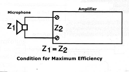
A first feature of great importance is the impedance that tells us how the microphone electrically behaves and how it delivers the electrical signal at its output.
A microphone may only transfer all the electrical signal that it generates to the external circuit, when its impedance is equal to the one at the input of the external circuit, that is, there is an "impedance matching" as shown in Figure 13.
If we connect a microphone that has a high impedance to an input of lower impedance of an amplifier, we can still get it to work, but there are losses, because the higher impedance microphones usually also provide a higher intensity signal.
This does not occur with a low impedance microphone: if we connect it to a higher impedance input of an amplifier there will not be driving, because its signal level is also insufficient.
The second main information is therefore the signal intensity supplied by the microphones which is given in millivolts (mV) or microvolts (uV).
The dynamic microphones of low impedance provide signs of microvolts order while the ceramic and crystal microphones provide signals in the range between 100 mV and 500 mV.
For the microphones and the common amplifiers to work, in most cases it is necessary circuits adapters called impedance matchers or pre-amplifiers.
The impedance matchers simply modify the impedance as the signal is delivered to the external circuit from a microphone, since the preamplifier also changes its intensity.
PREAMPLIFIERS
The purpose of a pre-amplifier is either increase the signal strength provided by a microphone so that it can drive an amplifier as well as match their impedance characteristics so as to achieve the desired performance.
Figure 14 is a simple example of a preamplifier for low impedance microphones (8 to 200 Ω) using only one transistor.
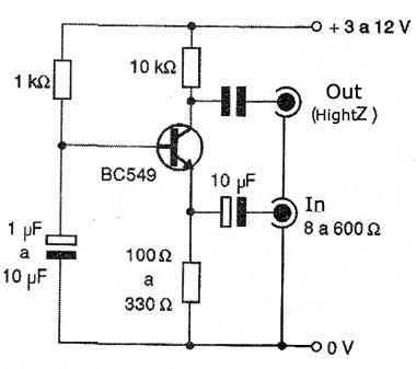
With this circuit, even an ordinary speaker or a dynamic microphone of a recorder can be used as amplifiers which require inputs entries around 200-500 mV.
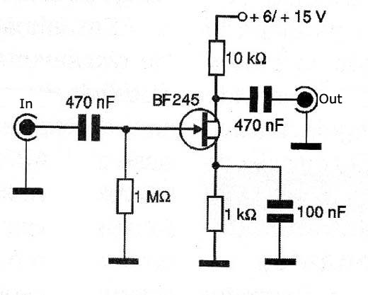
In Figure 15 we have a preamplifier circuit with a field-effect transistor for low sensitivity microphones of higher impedance, allowing its use with ordinary amplifiers.
Finally, in Figure 16 we have a circuit of a mixer which at the same time it amplifies the signals from several microphones it mixes them to deliver the mixture to a common outlet and then to an amplifier.
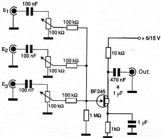
For this circuit ihe power can be made with common batteries or a battery, since consumption is very low.


