From Oersted's discovery that an electric current can create a magnetic field, the deeper study of electromagnetism has become of great importance for the development of various electrical and electronic devices such as solenoids, electromagnets, transformers, and so on. Thus, to get to the central point of this article, which is hysteresis, it will be important to review some of the theory of magnetism so that the reader can better understand the phenomena involved.
UNITS
The same way as in electricity we have several electric quantities such as current, voltage, power and resistance, in magnetism we also have different quantities which need to be defined and well differentiated so that the reader understands magnetic phenomena well. These magnitudes are usually measured in different units, which are named after the researchers who contributed to the development of this sector of science such as Maxwell, Gauss, Oersted, Gilbert, etc. We must then define the following quantities:
a) Magnetic flow:
This term is used to express the number of lines of force of a magnetic field which cross a certain area of ??a surface, as shown in Figure 1.
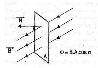
The magnetic flux is expressed by the letter H and can be given in maxwell in the CGS system, in weber (Wb) in the international system. The number of lines of force which crosses a surface per unit area is called magnetic flux density, or simply magnetic flux, is denoted by the letter B. Its unit is Gauss. Another flow unit used in the CGS system is Oersted.
b) Reluctance:
Reluctance can be considered the magnetic equivalent for resistance: it is the opposition which offers a material to the magnetic flux. We can more accurately define reluctance as the proportionality factor which exists between the applied magnetic force and the flux that results from this force on a material.
c) Permeability:
The way a material reacts by allowing the establishment of the lines of force of a magnetic field within itself is called permeability. We can compare this magnitude to the electrical conductivity of the materials in relation to the current. Permeability is indicated by the Greek letter µ (mu). It must be distinguished from the permeance that is the inverse of reluctance. The same way resistivity and resistance do not have the same meaning in Electrodynamics, permeability is equivalent to resistivity and permeance is the equivalent of resistance.
MAGNETIC MATERIALS
The several materials react differently when immersed in a magnetic field. This diversity of behavior allows us to classify them into two large groups: non-magnetic and magnetic (also called ferromagnetic). The magnetic materials, on the other hand, are classified as diamagnetic and paramagnetic, as shown in Figure 2.
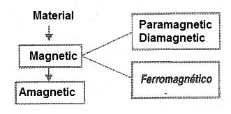
Diamagnetic materials have a slightly lower permeability than the unity (corresponding to air permeability) thus tending to resist magnetic induction by creating a magnetic field opposite to the external one. By placing a sample of such a material in a uniform magnetic field, see Figure 3, the field lines tend to disperse.
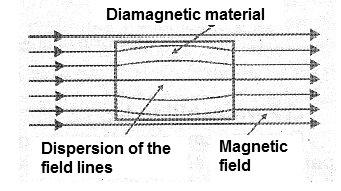
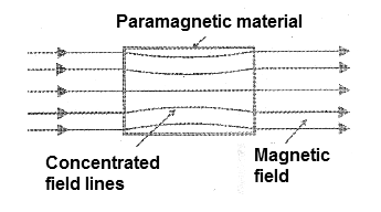
Diamagnetic materials are copper, gold, silver, mercury, antimony and bismuth. The paramagnetic materials have a permeability greater than the unity. This means that, placed in a uniform magnetic field, they magnetize in the same orientation of the external field, thus concentrating the lines of force, as shown in Figure 4.
Among the most common paramagnetic materials we highlight aluminum, magnesium, platinum, chromium, etc. Finally, we have ferromagnetic materials which are most important for applications in several electronic devices such as inductors, transformers, etc. These materials are characterized by acquiring a very large induced magnetism and with an orientation that coincides with the magnetizing field.
They then have a permeability, which, however, is not constant varying with the intensity of the magnetizing field. Materials such as iron have permeabilities of 2000 (depending on purity) and some alloys can reach levels of 50,000 (50,000 times greater than air permeability). An important phenomenon that occurs with these materials, which in some cases can retain the magnetism transforming into permanent magnets, is the magnetostriction. When subjected to a mechanical effort they have their permeability altered. So if we have a magnet, by subjecting it to mechanical stresses, its magnetic field will change. This property can be used in the construction of transducers such as microphones, pressure or mechanical stress sensors.
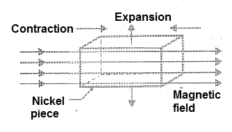
A material that has this property is nickel, which has a negative magnetostriction characteristic. That is to say, that when a mechanical stress is applied to the nickel parallel to the magnetic field, its permeability therefore also decreases its magnetism.
Likewise, if we apply a magnetic field to the nickel, it will contract, slightly in the direction of the lines of forces but will expand in the transverse direction, see example in Figure 5, thus keeping its volume constant.
ELECTROMAGNET
The density of the magnetic flux which can be created by an electromagnet depends on the number of turns of the winding as well as the intensity of the circulating current. This means that the density of the flux depends on the magnetizing force or the intensity of the circulating current. In Figure 6, we have a graph which represents the intensity of the field H with the density of the flow B forming what is called a magnetization curve and that depends on the material used as core.
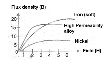
These curves are of extreme importance when one intends to use a material for the core of an electronic component such as a transformer or an inductor. It is through these curves that the dimensions of the cores of a transformer for an application are determined, as well as the number of turns of the coil and several other parameters for the construction of the component.
HYSTERESIS
As we have seen, the permeability of certain materials is not constant varying with the intensity of the field, and the magnetization curves also show just that. How this interferes with the behavior of a core or material that will be used within a variable magnetic field can best be understood from an imaginary experiment which we will now describe. To do so, we will use a variable power supply that will allow us to apply currents of any intensity in a coil with a core.
In the vicinity of this nucleus, we will place a scale that allows to measure the force of attraction on a piece of ferrous material, all according to the illustration of Figure 7.
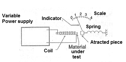
If we vary the voltage applied to the coil, we have an increase in the density of the flow which depends on the material, as we have already seen in the graph of Figure 6. This graph indicates that the increase in flux is not linear, that there is a point at which an additional increase of induction does not correspond to the increase of this flow. We say that, under these conditions, the nucleus is saturated. In this graph, the saturation begins at the instant the curves bend, and become full when they become horizontal.
However, we can go further if we make a graph where the magnetizing forces are placed as a function of the flux density, both when we increase and when we decrease the voltage applied to the coil, see Figure 8.
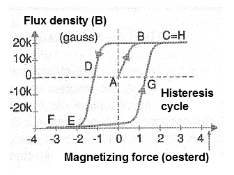
We then start from a zero voltage applied to the coil which contains a core of a ferrous material and we increase this current. Thus, starting from point A in the figure, the magnetizing force increases with the density of the flux, that is, with the intensity of the field produced by the coil until the moment we approach the saturation, when then an additional increase of that force does not provoke the increase in flow on the same scale. This point is indicated by B in the graph, reaching saturation in C.
What we observe now is that if we start from C to decrease the current in the coil in order to also reduce the magnetizing force, the way the flux decreases will not be the same, but it delays in relation to the one we obtained in the "outward”, but rather as shown by the curve to the point D where the action of a positive retentive magnetism on the core material is manifested. The cause of this delay characteristic in the "back" process of core degaussing has been called hysteresis (which is a Greek word meaning to retard).
Continuing to decrease the flux, we will see that the trajectory of the demagnetization curve will be displaced or retarded with respect to the outward, until the point D again in which we will have the null current applied or in which the magnetization is zero. At this point, even with a zero flux density, there is a negative remnant magnetizing force.
By reversing the direction of current flow and increasing its intensity, we observe the same effect until the points E and F in which again we reach saturation but with orientation of the inverted field. And, likewise, if we start from the point F and reduce the current until the density of the flux cancels out, we will arrive once again, to a point where we will have a positive remnant magnetism at the point G. Continuing now with the magnetization in the direction, we will reach the saturation point H. This curve is the characteristic of materials that are used as cores and is also known as BH curve, since in the axes are represented the density of the flow B and the intensity of the field H. In the indicated curve, the point where we have the saturation approximation is obtained with a sharp curve.
This type of behavior is the characteristic of good quality magnetic materials in which the states of magnetization can be changed abruptly with a relatively small variation of field intensity. The toroidal ferrite cores of the switched-source transformers use materials with these characteristics. Materials in which the curve is less pronounced or there is less hysteresis, such as those in Figure 9, are also useful being used in saturable reactors.
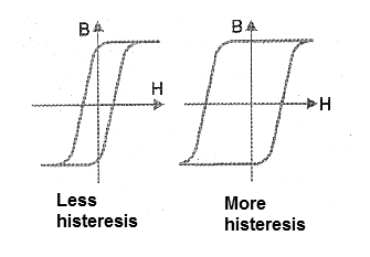
However, the fact that a material presents a hysteresis characteristic always means the existence of a remnant magnetism, which is not always desired in the electronic application. An alternative to cancel this remnant magnetism is the use of demagnetizing coils in which a strong alternating signal is applied to neutralize it. This is done, for example, in recording heads and reading sound devices and others. It is also important to note that the temperature of the material affects the permeability.
Thus, we have the point where the magnetic properties of the material practically disappear, being called the Curie Point. Likewise, at temperatures close to absolute zero, the resistance falls to practically zero values allowing the elaboration of super-magnets.


