Accurate reference voltages are important in many electronic applications as they work as parameters for measurement circuits, data acquisition and more.
While there are simple techniques for obtaining a reference, such as using zener diodes, the degree of precision required for an application may require much more elaborate configurations. In this article, we will see at the various types of configurations that can be used in these applications, with an analysis of their accuracy and reliability.
Zener diode
The simplest way to obtain a voltage reference is to use a zener diode in series with a resistor, as shown in Figure 1.
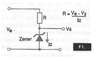
The zener diode keeps the voltage between its terminals constant, even when the input voltage varies within a certain range of values. However, this type of reference has some drawbacks, mainly due to the fact that a common zener diode, besides not being a component with an absolutely linear characteristic, undergoes significant changes in voltage which operates with temperature and, in addition, is already with a tolerance of 5%.
To give the reader an idea, we give in the table below the temperature coefficients of some common zener diodes as well as their dynamic impedance.
|
Zener Voltage (V) |
Temperature Coeficient (mV/°C) |
Dynamic Impedance (ohms) |
|
2,7 |
- 1,8 |
120 |
|
3,9 |
- 1,4 |
100 |
|
4,3 |
- 1,0 |
90 |
|
4,7 |
+ 0,3 |
85 |
|
5,6 |
+ 1,5 |
55 |
|
6,2 |
+ 2,0 |
27 |
|
9,1 |
+ 6,0 |
25 |
|
12 |
+ 8,0 |
35 |
|
15 |
+ 12,5 |
40 |
The internal resistance of a zener diode as regulator already causes the presented voltage to vary with the load voltage, as shown in Figure 2.
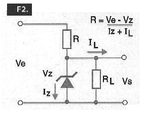
Within certain limits, we can use a zener diode in the setting indicated as a voltage reference, typically setting the current around 5 mA. Within a certain operating range, we may have a voltage reference which can be considered reasonable if the application does not require high accuracy.
We can improve the reference by using a configuration with an operational amplifier, as shown in Figure 3.
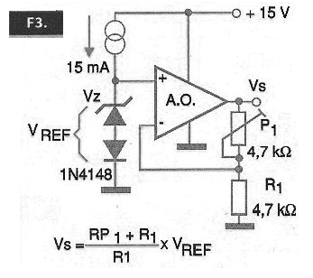
We power the zener diode with a constant current source and apply the reference voltage to an operational amplifier operating as a voltage follower or with a low gain which ensures a high input impedance to the circuit.
In this circuit, we can also vary one of the resistors of the feedback network controlling the gain and thus obtaining a different voltage than the one that can provide the zener. A major advantage of this circuit over its simple use of a zener diode is its low output impedance. The external circuit does not carry the reference, thus changing the value of the supplied voltage.
In a common application, the constant current source may even be a simple resistor calculated to provide a current of the order of 5 mA to the zener diode.
Integrated Circuits
Starting from the problems common references can present, we can elaborate circuits which compensate for the problems of variation of currents with temperature and also of voltages and more than that, we can integrate these circuits obtaining specific components for applications as voltage references.
The basic idea of an integrated voltage reference can be better understood if we take as a starting point the circuit of Figure 4.
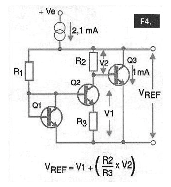
The pair of transistors Q1 and Q2 acts as a voltage reference, i.e., as a “virtual zener” where the voltage obtained depends on the transfer Characteristics of the transistors used according to the curve shown in Figure 5.
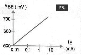
This circuit generates a band gap reference of approximately 1.25 V with excellent stability and is used in many integrated voltage regulators. In the circuit shown, the transistor Q1 actually functions as a zener, with the collector attached to the base, to provide a reference with a typical current of 1 mA.
The transistor Q3 is used as a driver and the constant current portion provides a 2.1 mA current so that the output transistor will have a 1 mA collector current.
The reference voltage obtained from this circuit (Vref) will be given by the sum of the voltage at R2 and Vbe3. Note that these two voltages have opposite coefficients of temperature so that one compensates for the other.
In practice, we can count on a good deal of voltage reference integrated circuits, the most common being those from National Semiconductor (Now in the Texas Instruments Group). In the table given below, we have some of them.
|
Integrated Circuit |
Vref |
Voltage tolerance (*)(+/-) |
PPM/oC Drift (max) |
Operating Current (mA) |
Output Type |
|
LM329B |
6V9 |
5% |
50 |
0.6 – 15 |
Shunt |
|
LM336B – 2.5 |
2V49 |
2% |
54 |
0.4 - 10 |
Shunt |
|
LM336B - 5.0 |
5V0 |
4.0% |
54 |
0.4 - 10 |
Shunt |
|
LM368 – 2.5 |
2V5 |
0.2% |
30 |
0.55 |
Series output |
|
LM368 – 5.0 |
5V0 |
0.1% |
30 |
0.35 |
Output up to 10 mA |
|
LM368 – 10.0 |
10V |
0.1% |
30 |
0.35 |
- |
|
LM385 |
1,235 – 5V3 |
- |
- |
13uA – 20 mA- |
Shunt |
|
LM385 – 1.2 |
1V235 |
2.4% |
150 |
15uA – 20 mA |
Shunt |
|
LM385 – 2.5 |
2V5 |
3% |
150 |
20 uA – 20 mA |
Shunt |
|
LM3999 |
6V95 |
5% |
6 |
06 – 10 mA |
Shunt
|
These integrated circuits basically operate in two ways to obtain the reference voltage. In one of them, there is an “integrated zener” on the chip itself, usually 6.9 V, which has good stability characteristics. In the other case, we have the integrated band-gap configuration, providing a typically voltage of 1.2 V.
Let's look at some practical circuits with these components, so that the reader has a better idea of their use.
LM329B
This integrated circuit can be used at an excellent voltage reference of 6.9 V, taking advantage of the fact that it is an integrated zener, according to the circuits shown in Figure 6.
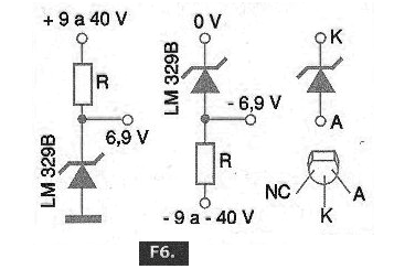
This circuit can operate with 0.6 to 20 mA currents in the zener diode and uses only an external resistor to fix this voltage. To obtain a different buffered voltage, we can employ this voltage reference along with an operational amplifier, as shown in the diagram in Figure 7.
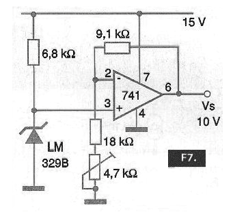
In this circuit, the gain of the operational amplifier can be adjusted to obtain the desired voltage, for example 10 V with the indicated circuit. A multi-loop trimpot allows a precise setting of the reference voltage of this circuit.
LM336B
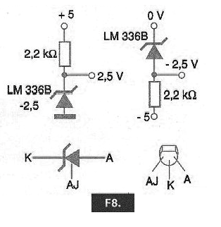
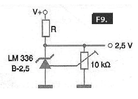
As shown in Figure 8, this integrated circuit is similar to the previous one, as it is basically a single chip adjustable zener. We have two possible configurations where the series resistor determines the current by the component. In this circuit, we have the fixed output voltages without the use of the adjustment input. To use the adjustment input, we use the setting in Figure 9.
Note, however, that this is not an adjustment in the broad sense that we can have any output voltage, but rather a trimmer, where we set the output voltage within narrow limits around the component reference voltage. For example, for the LM338B -2.5 V, the setting range is 120 mV around the 2.5 V output voltage.
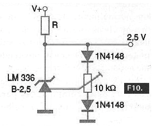
We can further improve the performance of this adjustment by adding a temperature sensor which compensates, as shown in Figure 10.
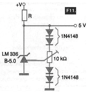
For the LM336B - 5.0 V we can have a temperature compensation and a wider setting of 500 mV using the circuit of Figure 11.
Of course, we can use this component along with others to get more elaborate applications of a voltage reference. A first possibility is a circuit which accepts a wider range of input voltages to obtain a fixed output reference, as shown in Figure 12.
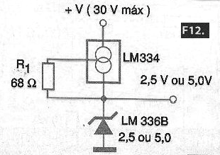
This circuit is based on the LM334 which is a constant current source and which allows, together with the LM336B, to obtain reference voltages of 2.5 V or 5 V, depending on the component used. This circuit supports input voltages up to 30 V.
In Figure 13, we have a circuit that aims to obtain a precision rectangular signal for circuit adjustment. It is, therefore, a modulated voltage reference, ideal for calibrating oscilloscopes, digital interfaces and data acquisition systems.
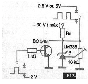
The peak voltage obtained from this circuit depends on the voltage reference integrated circuit used which can be either 2.5 V or 5 V.
LM368
These components, in their three versions of 2.5, 5.0 and 10 V, have a band-gap internal voltage reference and a power step which can provide output currents up to 10 mA. The output voltage is determined by the component suffix.
The LM368 integrated circuit is supplied in both an 8-pin DIL enclosure and a metal enclosure. In Figure 14, we have the basic application of this component, for a low noise voltage reference.
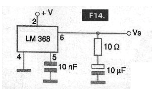
The capacitors and resistor form a filter circuit which reduces noise. In Figure 15, we have the way of using the adjustment input, which also in this case has a narrow range of action on the order of 1% of the voltage to obtain a high precision output voltage.
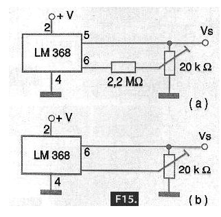
To obtain a wider adjustment range, the circuit of Figure 15 can be used.
For LM368-2.5, for example, with the indicated circuit, reference voltages can be obtained from 2.2 V to 5.0 V and for LM368-5.0 output voltages from 4.5 V to 6.0 V can be obtained with this same circuit.
In Figure 16, we have an interesting configuration that using two references of the indicated type can be used to obtain a symmetrical voltage reference with only one current limiting resistor.
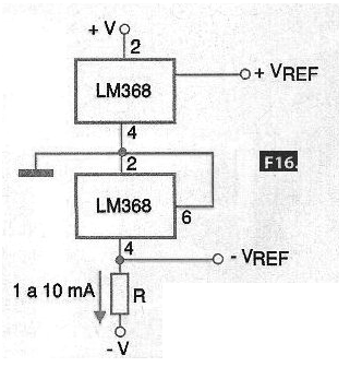
The resistor must be calculated to obtain a current of 1 to 10 mA in integrated circuits which work as voltage reference. To obtain two reference voltages with less components as possible, we can use the circuit of Figure 17.
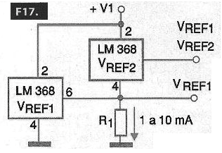
In this circuit, the resistor is calculated to obtain a current on the order of 1 mA or more for the chosen reference voltage.
LM385-1.2
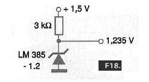
It is a three-terminal SOT54 (Small Outline Transistor) enclosure voltage regulator, but only two of which are used. As shown in Figure 18, it behaves as a precision zener providing a 1.235 V reference from very low voltages, such as a single 1.25 V battery.
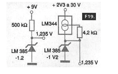
For a higher voltage supply, 9 V for example, we can use the circuit of Figure 19. In this same figure, we show the version that uses a constant current source and thus enable the operation of the circuit over a wide range of input voltages.
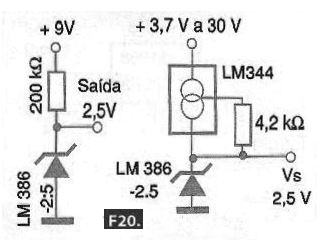
For the 2.5 V version (LM385-2.5), we have the circuits shown in Figure 20.
The LM385 version (without suffix), has an adjustment terminal and can operate in two basic configurations as shown in Figure 21.
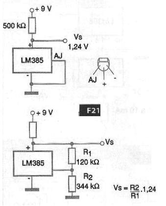
In the first, it operates as a fixed reference of 1.24 V which is given by the band-gap regulator while in the second case, with the help of a resistive divider it is possible to program the output voltage to a higher value.
This value can easily be calculated by adding 1.24 to the voltage provided by the resistive divider. According to the formula given next to the diagram. Note that this integrated circuit also comes in a three-terminal SOT-54 enclosure.
LM3999
What distinguishes this device apart from the other integrated circuits, which act as voltage references, is the presence of a temperature compensation circuit. In Figure 22, we have the housing and the equivalent internal circuit.
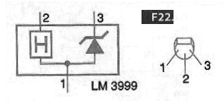
This device has a temperature coefficient of 0.0002% per centigrade degrees and operates with currents from 0.6 mA to 10 mA. The reference voltage is 6.95 V. In Figure 23, we have a typical circuit of application of this component.
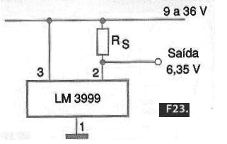
The resistor must be calculated so that the current in the zener is within the range allowed by the component. For a buffered voltage reference, we can use the configuration shown in Figure 24 which makes use of an operational amplifier.
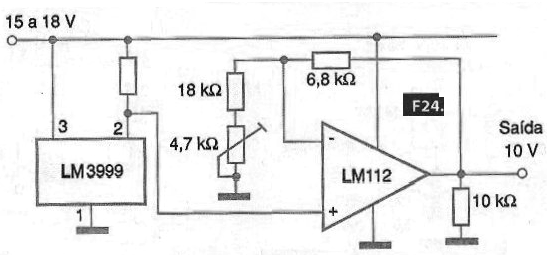
The operational amplifier voltage gain can be adjusted in the trimpot to obtain voltages different from that provided by the LM3999 internal zener. In the example, the voltage will be set to a value around 10 V.
Note that this circuit input can be between 15 V and 18 V and the LM3999 internal temperature compensation is used. This circuit has a precision high enough to be used in the calibration of laboratory instruments.
Conclusion
Voltage references are very important circuits mainly in the design of measuring instruments and for their own calibration. In this article, we made a brief analysis of the main types, with a special focus on the National Semiconductor integrated circuit line (www.national.com) which has a very broad line of these components.
We suggest that the reader visits this company's website not only to have access to the complete datasheets of these components, which is important for a design, but also to learn about any new types that are being released or have recently been released.


