There are certain basic configurations in electronics such as time circuits, filters and of course resonant circuits whose knowledge of the working principle is essential for professional practice.
Thus, in this article we will explain in a very detailed and, therefore, didactical how functional the parallel LC resonant circuits, which have the configuration shown in Figure 1.
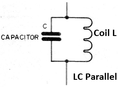
Before we move to the operation of the complete circuit, let us analyze the operation of the two components which form it.
The Capacitor
A capacitor is basically formed by two boards of conductive material, called armatures, separated by an insulating material, called dielectric, as shown in Figure 2.
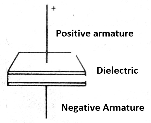
When we connect a capacitor to a direct voltage source, a generator, we find that the capacitor armatures are charged with opposite signal loads.
When we connect the capacitor armatures, through a conductor wire which presents some resistance, the discharge occurs with the circulation of a current.
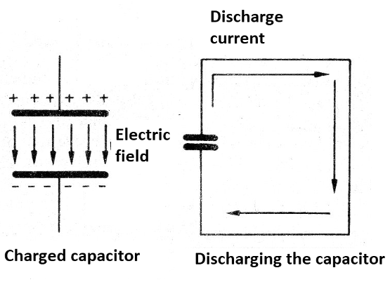
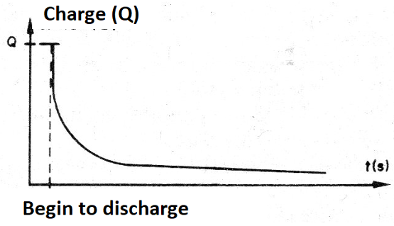
The current lasts until complete discharge occurs. Thus, during unloading the load and voltage on the armature gradually decreases according to a discharge curve as shown in Figure 4.
Connecting a capacitor to an alternate current (AC) circuit it will behave differently. When the voltage has a polarity, the armature charges with loads which correspond to this polarity.
When the polarity is reversed in the next half cycle of the AC, the capacitor discharges and charges again with the polarity reversed. In other words, in an AC circuit the capacitor will be charging and discharging rapidly following the polarity inversions of the current.
This means that in an AC circuit there will always be a current flowing through the capacitor, coming and going in the polarity reversing charge and discharge cycles. If we then analyze the capacitor in an AC circuit, we see that it somehow allows the current to circulate and this to a greater extent as the charge and discharge, i.e., its value.
This current also depends on the frequency, as with higher frequency the loading and unloading will be faster with a more intense current flowing. We can then associate the capacitor to a reactance, that is, the opposition that it presents to the current and that depends on its value and the frequency of the current, according to the graph in Figure 5.
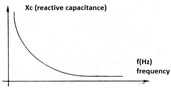
See then, that the higher the frequency, the current can flow better through the capacitor and with it the less opposition it has to its circulation, that is, the lower the reactance.
The inductors
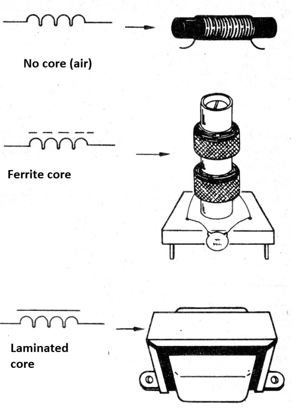
Inductors, shocks, or coils, as they are also called, are wire loop components which can be wound into cores with ferrous material or left without core (air core).
These components can have many aspects, as shown in Figure 5.
To understand how an inductor works in a AC circuit, let's take as an example the circuit of Figure 7.
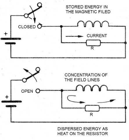
Assuming that the resistance of the wire used in the inductor is much lower than the resistor resistance in parallel, when we close the switch, the circulating current will be much higher in the inductor. This will create a magnetic field for this component, which has its lines expanding through the space.
The current increases gradually until it stabilizes when the field completes its expansion. When we open the switch and the current ceases, the magnetic field lines do not disappear immediately.
They contract rapidly, inducing in the inductor a voltage contrary to that of the current which created them. In other words, at the ends of the inductor appears a voltage that circulates a current through the load resistor.
This current rapidly decreases in intensity until it disappears when all the lines of force in the magnetic field contract. An interesting experiment to show this fact can be made with a small reactor used with fluorescent lamps, as shown in Figure 8.
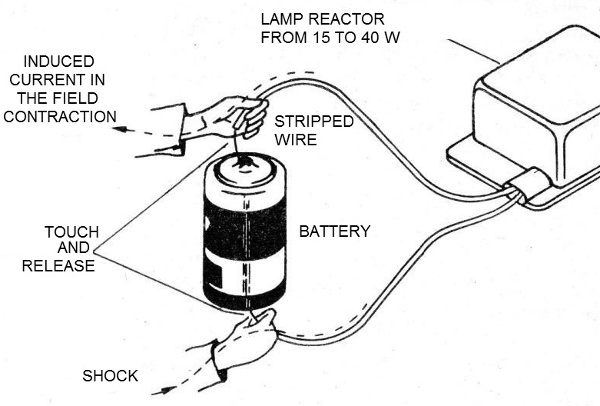
When we touch the reactor wires to the stack, current flows and the field is created. When we release it, the field contracts, generating a much higher tension than the one that created it, causing the person holding the wires to have a shock. Just as the capacitor behaves differently when connected to the AC network, so does the inductor. When applying an AC to an inductor, the current inversions constantly cause the created field to invert, as shown in Figure 9.
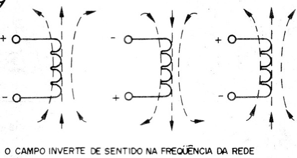
When the voltage is applied to the inductor, it presents some opposition to the current variations. The greater this opposition is, the faster the variation.
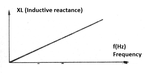
Thus, the inductor presents an opposition to the circulation of an AC which increases with the frequency. This opposition is called inductive reactance, measured in ohms and increases with frequency as shown in the graph in Figure 10.
The Resonant Circuit
In order to understand how a resonant circuit works, we must start by understanding what resonance is. All bodies tend to vibrate more strongly at a frequency which depends on their shape, the nature of the material it is made of, and its dimensions. When we hit a glass, a tuning fork or vibrate a guitar string, these bodies vibrate at a unique frequency which is their resonant frequency. This resonance phenomenon also occurs with electrical circuits, and the one formed by a capacitor in parallel with an inductor is just one of them.
The two components have opposite behavior, as we have seen, one has a reactance which decreases the frequency and the other has a reactance that increases the frequency. If we take into account the calculation of their reactances, as shown in the formulas below, there is an important point for the values found: the points where the reactances match.
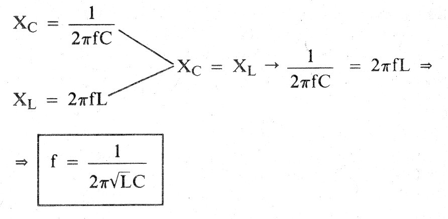
Thus, for a given capacitance value and a given inductance value, there is a unique frequency at which the reactances match. This frequency is the resonant frequency of the circuit and it tends to oscillate more easily on it.
We then see in Figure 11 that if we apply frequency signals which move toward the resonance, the circuit reactance increases until it reaches a maximum.
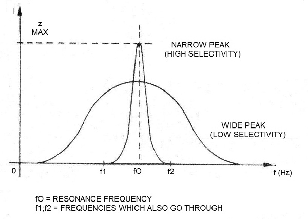
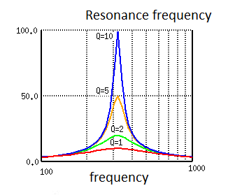
At this maximum point, the circuit reactance is theoretically as its maximum, i.e., it has infinite resistance to the signal. In practice, this does not happen as inductors and capacitors are not perfect and the curve may be wider. From the resonance point, increasing the frequency further, the reactance drops again as shown in the same figure. When a resonant circuit has a narrow peak response we say that it has high selectivity, that is, it can separate well the frequencies other than the resonance.
A circuit with low selectivity also lets pass, but with less intensity, the frequencies near the resonance. One factor which influences the selectivity of a resonant circuit is that the inductor wire has a certain resistance. The selectivity of a circuit is measured by the factor Q.
The factor Q
If we analyze the resonant circuits, in the ideal condition, they should only respond to one frequency and reject the others. In practice, however, the presence of parasitic resistances in the circuit makes it tend to have less acute response curves, which determines the quality factor or Q factor, which measures its selectivity.
Thus, as shown in Figure 12, a circuit with a higher quality factor, has a higher selectivity, responds better to a certain frequency and rejects the others.
Note, however, that in practice, we should not have a tuning circuit whose selectivity is maximum, as this will also means that in modulating the received signal, when it shifts from its frequency, we will have its loss.
The factor Q is given by the formula:
Where:
Q is the Q factor
R is the resistance associated with the circuit in ohms
C is the capacitance in farads
L is the inductance in henry
The Tuning Circuit
A first important application for LC resonant circuits is as a radio receiver tuning circuit, as shown in Figure 13.
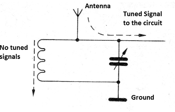
Signals from all stations intercept the antenna inducing high frequency currents at their frequencies. These signals are led to the tuning circuit formed by the coil and a variable capacitor.
We then set the variable capacitor so that the circuit only resonates at the frequency of the station we wish to hear. This means that the resonant circuit will have a low resistance (impedance) for signals from all stations that will then go to the ground, except that of the selected station.
This signal, finding a high resistance (impedance) is diverted and taken to the receiver processing circuits, where it will be demodulated and will have the information corresponding to the sounds extracted.
The Oscillating Circuit
The LC circuit works just like its mechanical equivalents like the tuning fork, the string of an instrument, or even a crystal bowl. When electrically driven, it tends to oscillate at a single frequency, and that frequency is the resonant frequency.
To understand what happens, let's start from the circuit of Figure 14.
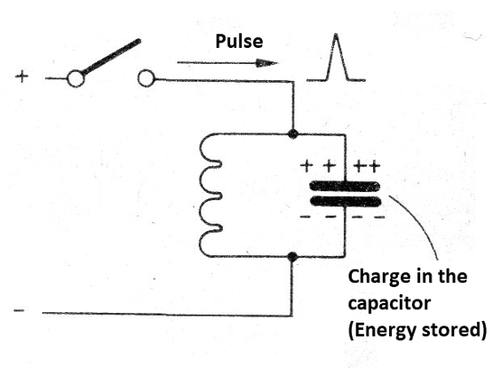
When we close the switch and open it quickly, the rapid variation of the current prevents its circulation by the opposing inductor, but with this the capacitor charges. We now have an electric field between the circuit boards and the energy is stored in the capacitor.
But this charge is short-lived, as soon as the voltage stabilizes in the capacitor, it begins its rapid discharge through the inductor. Under these conditions, as shown in Figure 15, a magnetic field is created and the energy stored in the capacitor transfers to it.
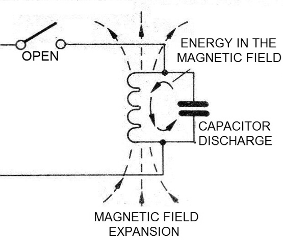
This does not last long either because, as soon as the capacitor discharges, and the energy is all in the inductor field, its power lines begin to contract, inducing an inverted voltage at its terminals, as shown in Figure 16.
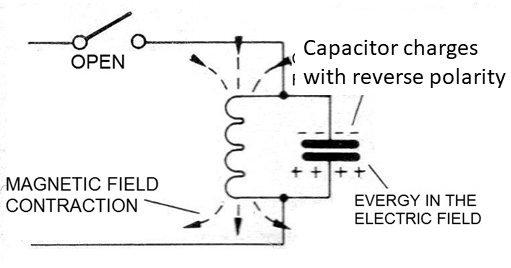
This voltage will then charge the capacitor again, but now with the polarity reversed. We then have the transfer of energy from the magnetic field of the inductor into energy from the electric field of the capacitor. A new capacitor discharge cycle then begins with its discharge through the inductor.
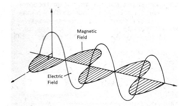
The speed in which this process occurs is precisely given by the resonance of the circuit and if we connect this circuit to an antenna, we will produce electromagnetic waves. These waves, as the name suggests, consist of alternations of the electric field and the magnetic field, as shown in Figure 17.
In practice, the oscillations do not continue forever. The resistance of the wires and other losses, gradually cause the oscillation produced to lose its intensity until it completely disappears.
In other words, the circuit in this simple way produces a damped oscillation. To keep the circuit oscillating, we need to have some feature which restores the energy that is being lost or used to drive an external circuit, or to be transmitted by an antenna. We can do this through a feedback circuit and an amplifier which has a certain gain, as shown in Figure 18.
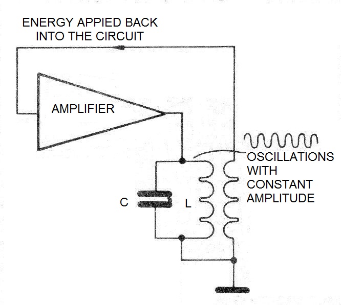
With this circuit, we keep the circuit oscillating at its resonant frequency. We can compare the oscillations produced to the oscillation of a pendulum, as shown in Figure 19.
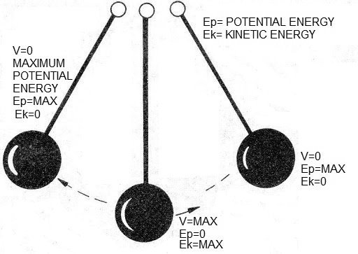
When the pendulum is in the extreme positions, stopping for an instant, all the energy it has is potential. When it moves and at the lowest point of the trajectory, it has the highest speed, all the energy in the system is kinetic. These energies constantly alternate, as in the electric circuit where we have energy in the electric field and energy in the magnetic field.
Conclusion
On the website, the reader will find a huge amount of circuits which employ both coil and capacitor tuning as well as oscillators of all kinds. It will be interesting to look in the mini-project section for one of these circuits to assemble into a protoboard to study the resonance phenomenon.


