What a wonder it would be if we could isolate ourselves from the world when a loud clatter of tools, the noise of a big city, or the loud talk in an adjoining room annoyed us.
Meditation, concentration and even sleep would be much easier, without the need of a very huge effort.
In fact, this is possible through something we call "mind shield" and that is nothing more than something that can, in a way, cancel the effects of excessive noise and help in concentration, meditation and even sleep.
The idea is simple: if the environment noise can hinder concentration, there is a type of signal that can be superimposed on this noise, that is, a new form of noise, which cancels it and at the same time, by not bringing any information , does not prevent the concentration of the person.
This is white noise, which can be described as the noise of the sea, which is similar to a continuous sizzle, but which actually has important properties, already proven in many surveys.
In fact, all readers should agree that the noise of the sea, or the noise of the rain, has a restful "thing." And, if the reader observes well, he/she will see that this noise can even cancel the effects of a noisy place, reducing the effects of irritating sounds, such as beats, conversations, motors, etc.
The white noise does not necessarily need to be achieved from natural sources such as the sea, strong wind or rain. The reader may well have a generator for this noise and use it as a kind of mental shield when needing a higher degree of concentration that the environment noise does not allow
It will suffice to connect the white noise generator, which we call the mental shield itself, to a good amplifier and adjust its level so that what disturbs you is canceled.
In this way, nothing will divert your attention, being easily achieved the total state of concentration, sleep or "shutdown" desired.
The assembly of the device is very simple and can be connected to any audio amplifier of 1 W. (Figure 1)
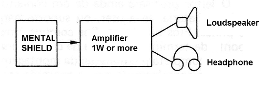
The power of the amplifier is not important in the case, and only a higher level is required if the reader needs to cancel noise from a large room. For personal use, just stay close to the speaker!
HOW IT WORKS
The main characteristic of a white noise, such as rain or sea, is that it has no characteristic, that is, it does not have a defined waveform, as suggested in Figure 2.
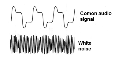
This lack of standard, that is, the non-existence of periodicity, is that it does not make an interpretation on the part of our brain, hence its relaxing properties.
In order to produce such noise, we do not need something that oscillates, nor of any device that has a defined pattern of operation, quite the contrary.
We need something that has random behavior in which no pattern can be defined.
This is easily accomplished by the shock or vibration of the particles of a material that is at any absolute above zero temperature.
Above -273° C, all the particles of a material vibrate, by what we call thermal vibration, and they collide in totally random way.
In a semiconductor material, these vibrations can result in currents of the same pattern and, after being amplified, result in white noise.
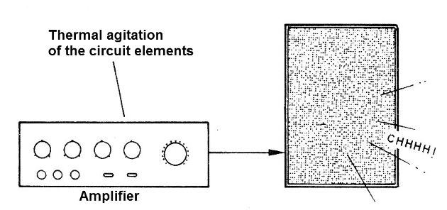
The reader can see this phenomenon by connecting an unsigned amplifier and opening its volume. The wheezing that appears is a consequence of the thermal vibration itself of the circuit elements, which is amplified and reproduced. (Figure 3)
For our circuit, we can use a simple transistor as the source of white noise, and it is connected as shown in Figure 4.
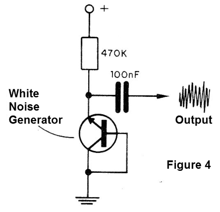
The current produced by the shocks of the charge charges between the emitter junctions and the base of a common transistor is used in this case.
The collector is connected together with the base, since we do not need amplification in this case.
The noise obtained has, however, a very small intensity, requiring amplification.
Taken from the emitter of the transistor, this white signal is taken to two amplifier steps, now with common transistors, as shown in the final diagram.
In the last stage, the white noise already appears with great intensity, being able to be played in a conventional amplifier to obtain enough power to drive a loudspeaker.
The circuit is supplied with a voltage of 9 V, which can come from a standard or 6-cell battery. The current consumption of the circuit is very low, guaranteeing great durability for the batteries.
Therefore, and also because of the noise, we do not recommend powering through a source.
MATERIAL
All the material used in the assembly is common and, in addition, low cost.
We start with the box which should preferably be of metal, to work as a shield and avoid the capture of the rumbling of the local network which would overlap with the white noise, thus damaging the operation of the apparatus.
The mesh of the shielded or negative wire of the source will be conected to the box.
The original transistors are BC548, but equivalents, such as BC237, BC238 or BC547, can be used.
The resistors are all 1/8 W or larger with any tolerance and the capacitors are all ceramic or polyester.
S1 is a simple switch of any type to switch the appliance on and off.
The reader will also need a battery connector, if any, or a 6 battery holder. Shielded wires, common wires, a terminal bridge or printed circuit board complete the assembly material.
As a complement to the operation, a shielded cable will still be needed, having at one end a RCA pIug and at the other a pIug according to the AUX input of the amplifier that will be used.
ASSEMBLY
In Figure 5, we have the complete diagram of the device, being necessary for its assembly the common tools. Use a small power welder.
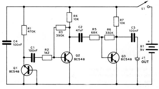
The terminal strip version of the terminals is shown in Figure 6. In this version, care must be taken with its fixing in the box, and it should be isolated.
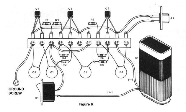
Only the extreme terminal on the left should contact the housing with a screw.
The printed circuit board version is shown in Figure 7.
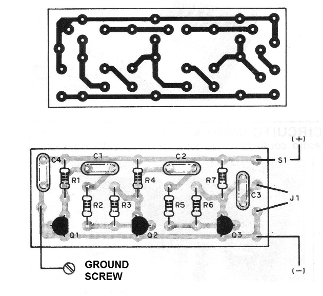
The fixing of the board can be done by means of spacers.
In the assembly, follow the following sequence:
a) Weld the transistors first. Note that all of them have a right position given by the flat part and also that Q1 has the interconnected base and collector terminals. Be quick in this operation.
b) Then, weld the resistors. These components have the values ??given by the colored bands according to the material list. In the bridge version, fold and cut the terminals to the appropriate lengths.
c) Weld the capacitors quickly, as they are sensitive to heat. Look carefully at the values. For 100 nF you can see the code 0.1 or 104 and for 47 nF you can see the 0.05 or 473 mark.
d) Make the three interconnections on the bridge with pieces of wire, if this is your version. These interconnections should be short.
We will now work with the external components.
e) Connect jack J1. If it is too far from the bridge or board, in view of the box size, use shielded wire. The mesh is in the Q3 emitter.
f) Connect the battery holder or connector, observing its polarity. The black wire goes to the board or bridge and the red wire (+) to the main switch S1. Then attach the J1 output jack and also the battery holder or connector on the case.
This will allow the unit to be ready for use.
TEST AND USE
Connect the unit to an amplifier as shown in Figure 8.
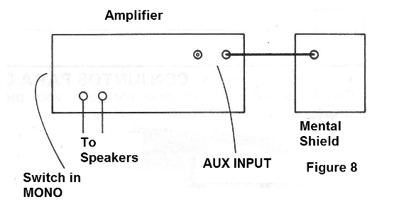
Turn on the amplifier at medium volume, then press S1.
The amplifier must reproduce a loud hissing, similar to the noise of the sea or the rain.
If there is rumbling, check the shielding of the wires, or the connection to the ground wire box. If necessary, replace the internal J1 output wires with shielded wire.
To use the device, simply adjust the white noise level to the point where the environment noise, which prevents the concentration, is "erased".
Then just concentrate, meditate or even sleep!
Q1, Q2, Q3 - BC548 or equivalent - Silicon NPN transistors
C1, C3, C4 - 100 nF - ceramic capacitors
C2 - 4.7 nF - ceramic capacitor
R1 - 470 k x 1/8 W - resistor (yellow, violet, yellow)
R2 - 1k2 x 1/8 W - resistor (brown, red, red)
R3 - 390 k x 1/8 W - resistor (orange, white, yellow)
R4, R7 - 10k x 1/8 W - resistors (brown, black, orange)
R5 - 68 k x 1/8 W - resistor (blue, gray, orange)
R6 - 330k x 1/8 W - resistor (orange, orange, yellow)
J1 - RCA jack
S1 - single switch
B1 - 9 V - battery or 6 small batteries
Miscellaneous: printed circuit board or terminal strip, mounting box, shielded wire, common wire, battery connector or 6 batteries, etc.


