Light seeking light doth light of light beguile.
William Shakespeare (1564-1616)
The special light sources described here can be used with many of the other projects, adding new effects and helping the researcher to make new discoveries.
Simple Light Detector
Some paranormal phenomena can involve light variations too slight to be seen by the human eye. A device with greater sensitivity than the human eye, and one that also can detect UV and IR light, is a very useful tool in the paranormal experimenter’s lab. The circuit described here is a very sensitive photodetector powered from AA cells or a battery, and it can be used in many studies as suggested below.
Experiments
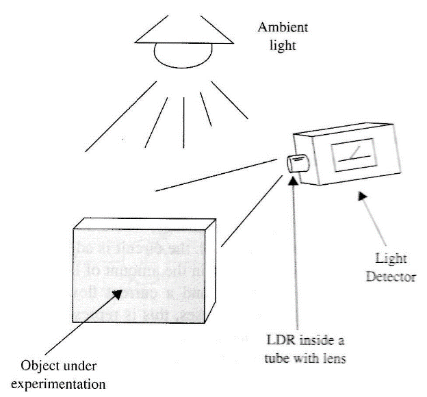
■ The ESP researcher can use this circuit to detect special abilities in a subject by variations in the amount of light falling onto a sensor. Filters in front of the sensor can be used to detect changes that occur only in specific light wavelengths (colors). The basic experiment is to monitor IE during ESP experiments, the amount of ambient light is affected or if the light reflected by the object on which the subject concentrates his mind changes (Fie. 1).
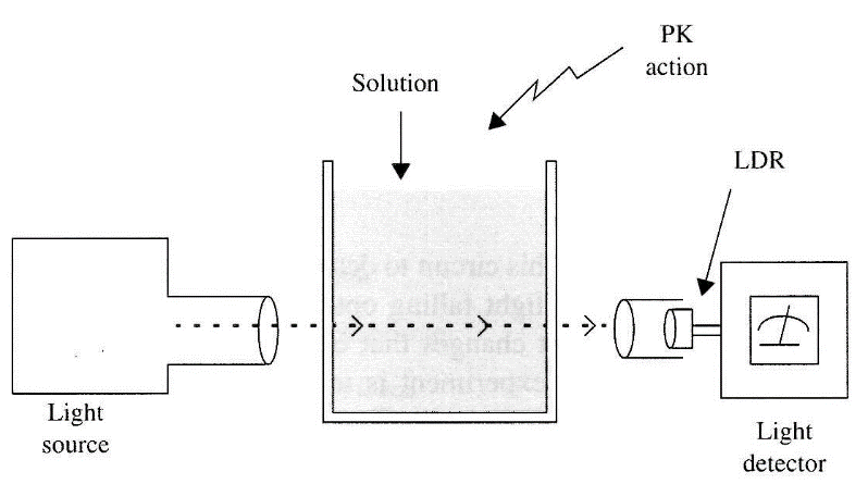
■ Some experiments in psychokinesis are suggested by Fig. 2. First, the person can try to induce variations in light by directly affecting a source such as a common incandescent lamp. Or the person can induce variations in the amount of light passing through a medium such as a glass filled with a transparent or translucent solution, or even a solid piece of glass. Or the person can attempt to induce variations in the light reflected by a mirror.
■ Any changes in ambient illumination can be detected if they occur in conjunction with a subject achieving the fourth state of consciousness or trance. The subject can be illuminated by a light source, with the device used to detect any change in the amount of light reflected by his body while in the trance or fourth state of consciousness. This is an important experiment to perform.
■ The manifestation of many paranormal phenomena are followed by changes in physical parameters in the ambient. For example, variations of the ac power line voltage can cause "flickering" of lamps, magnetic fields, and electric charges. To monitor these phenomena, an electroscope (Project 34) can be useful, along with a device that can detect small changes in the ambient light.
■ The changes in the transparency of a solution with bacteria can be detected in a PK experiment or others.
How It Works
For the sensor, our circuit uses an LDR or photoresistor (CdS cell). This device has a resistance that changes with the amount of light falling onto the sensitive surface.
An LDR is more sensitive than a human eye, as it can detect amounts of light that are not detectable to us, and it also can detect light in part of the ultraviolet and the infrared ranges. The use of optical filters in front of the sensor (LDR), by making the circuit frequency selective, can help when working with light of one wavelength or frequency. It is also possible to add a polarization filter in front of the device.
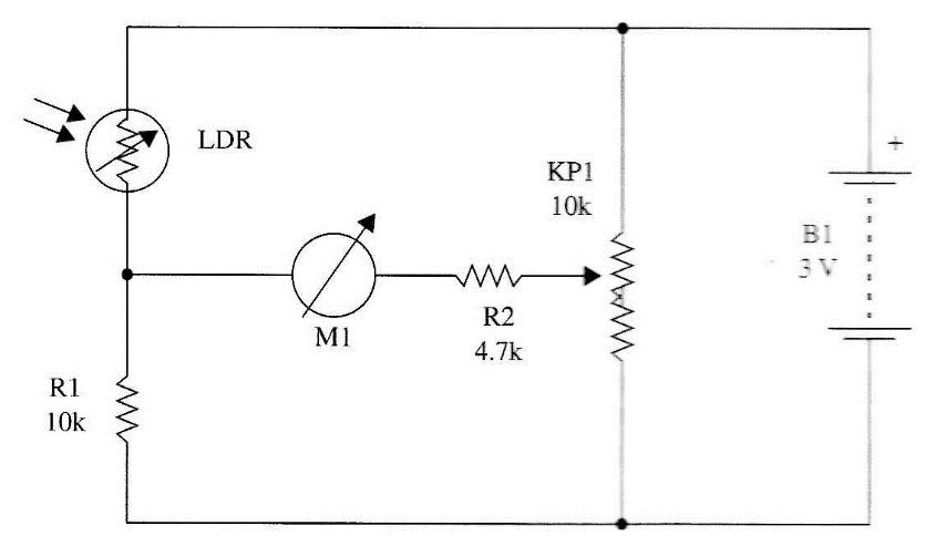
The LDR is plugged to a Wheatstone bridge, where the null detector is a cur-rent meter. At a predetermined light level, the circuit is adjusted to the null point (zero current on the meter). Any change in the amount of light falling on the sensor changes the bridge's equilibrium, and a current flows through the meter. When the light level increases or decreases, this is represented as movement of the meter's needle in the corresponding direction. Using a meter with zero in the center of the scale, it is possible to detect very small changes of light intensity in either direction.
The circuit is powered from two AA cells, and the current drain is very small. The cells can last for many weeks or even months.
Assembly
Figure 3 - shows the complete diagram of the light detector. As the circuit uses very few components, it can be mounted on a terminal strip.
The meter is a 50-0-50 pA type, but common types with scales ranging from 50 to 200 pA without zero in the center can be used. You only have to adjust P1 to a middle scale indication when using it.
The LDR or CdS cell can be of any type. It can be placed inside an opaque cardboard tube to increase sensitivity and directivity. A convergent lens in front of the device is another aid for increasing directivity and sensitivity. The LDR must be placed at the focal point of the lens.
All of the components can be installed in a small plastic or wooden box.
Testing and Using the Circuit
Place the cells in the cell holder. The on/off switch is not necessary.
Adjust P1 until you obtain a mid-scale indication on the meter. The LDR must be pointed to an illuminated spot. When you pass your hand in front of the sensor, the change in the light falling on it will cause the meters needle to move.
When using the device, colored filters or polaroid filters can be placed in front of the sensor. Pieces of cellophane are good color filters that can be used in many experiments. Changes in the amount of light in an ambient can be detected by the movement of the meter needle.
Suggestions
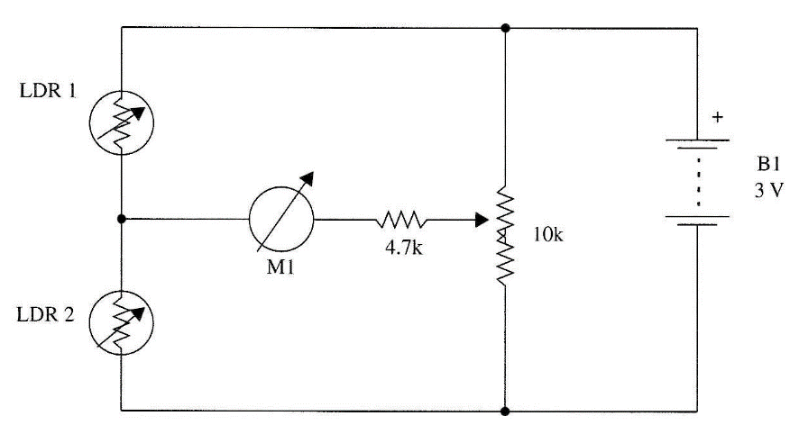
■ Two LDRs can be wired to the circuit to make a differential detector system. The circuit shown in Fig. 4 detects when the light levels in two different places change by different amounts.
■ Add scale indications to the meter (+) and (–) to indicate when the amount of light increases or decreases.
■ Change R1 according to the amount of light used in the normal experiments. When working in bright ambient, use a 10 kΩ resistor. In dark ambient, increase this resistor to 100 kΩ.
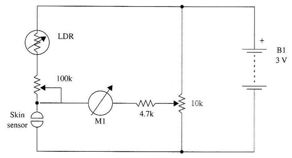
■ Use a resistance sensor to equilibrate the bridge from your skin resistance as shown in Fig. 5. This configuration can be used in experiments involving biofeedback, PK, and transcendental meditation.
Resistors
R1 10 kΩ, 1/8 W, 5%—brown, black, orange
R2 4.7 kΩ 1/8 W, 5%—yellow, violet, red
Miscellaneous
P1 10 kΩ potentiometer
LDR Common light-dependent resistor or CdS cell (see text)
M1 50-0-50 µA meter (see text)
B1 3 V, two AA cells
Terminal strip, knob for P1, cell holder, plastic or wooden box, optical filters, wires, solder, etc.

