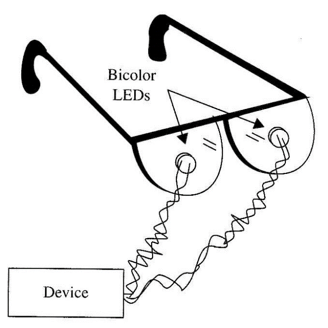
Placed near the subject's eyes, the flickering effect of the LEDs can induce him into trance, fourth state of consciousness, or simply into a relaxed state. The LED flashes are powerful enough to be sensed even when the subject closes his eyes.
In addition to applications aimed at relaxation or hypnosis, the circuit can be adapted for use in other paranormal experiments. For instance, the visible light LEDs can be replaced by IR (infrared) devices to see if they have any effect on paranormal experiments involving ESP. They can be used to determine if the subject can sense radiation at wavelengths outside of the visible spectrum.
The circuit is powered from AA cells or a 9 V battery and is housed in a small plastic box, so it can be transported to any desired location for the experiments.
With appropriate modifications, the following experiments can be performed with this project.
Experiments
The hypnotic glasses can be used to assist the subject in achieving a special mental state in experiments that aim for relaxation, the fourth consciousness state, or even a trance. An interesting suggestion is the use of infrared LEDs to see if in-visible light can have some effect on the subject or if he can detect it via a "sixth sense." The LEDs can also be mounted on a panel. The subject must concentrate on them to achieve the special mental state required for the experiments.
Although the frequency or flash rate of the LEDs is an intrinsic property of the circuit, in a PK experiment, the subject can try to alter it with his mind. Another person involved in the experiment (a sensitive) can try to detect those changes by observing the flashing LEDs. The circuit can also be used to help the subject to achieve a required mind state before starting with other experiments.
In radiesthesia experiments, the effects of flashing LEDs on a person can be detected or monitored via the use of a pendulum. The researcher can also try to use a pendulum to change the flash rate.
In transcendental meditation and biofeedback, the fourth state of conscious-ness can be achieved using this circuit as described in the beginning of the text as a basic application for this circuit. The experimenter can also investigate how the LED flashes can affect the time required to enter the special mental state.
In experiments involving plants and animals, the flashing LEDs can be used as a stimulus to produce some paranormal effect. For example, how will a plant leaf react to some kind of paranormal stimulus if it is placed in a dark box and illuminated only by the flashing LEDs?
How It Works
This circuit is also based on an oscillator using the 4093 CMOS IC. One of the four gates of the IC is used as a low-frequency oscillator. The frequency range of about 0.1 to 5 Hz is determined by Cl and adjusted by Pl. The digital signal pro-duced by this stage is applied to two other stages using the remaining gates of the IC.
One stage is formed by a single gate that operates as a buffer-inverter, driving the LED of one color (green, for instance). The LED will glow when the output of this stage goes to the high logic level.
The other stage is formed by two NAND gates of the 4093 IC that are also wired as buffer-inverters. This way, as the applied signal is inverted and unin-vetted again, the output of this stage goes to the high level when the output of the other stage goes to low. This stage drives the other color LED red. for instance)
This means that when one output is high, the other is low. and vice versa. As the circuit changes its state at a rate determined by the oscillator, the LEDs flash in an alternating manner.
Assembly
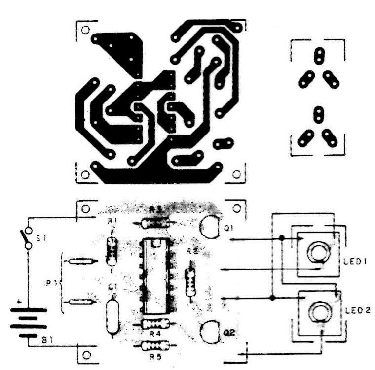
Figure 2 shows the complete schematic diagram of this device. The project can be mounted on a small printed-circuit board as shown by Fig. 3.
Bicolor LEDs (red and green or red and yellow) are suggested. but if you have difficulty in finding them, you can use common LEDs Any color can be used to suit the experiments you have in mind. You can even test different combinations of colors in your experiments.
R4 and R5 determine the brightness of the LEDs. For a 6 V battery, we recommend a 470 S2 resistor. For a 9 V battery, we recommend a 1 kΩ resistor. But, in some experiments, the amount of light produced by the LEDs must be reduced. Very low light levels are necessary to avoid sensory overload to the subject's eyes. To accomplish this, you only have to increase R4 and R5 to values up to 22 kΩ. Higher values also imply lower current drain from the power supply, extending its life.
The circuit can be installed in a small plastic box with the LEDs placed on common glasses, attached to the lenses. Wires 100 cm in length are used to connect the circuit to the glasses.
Testing and Using the Circuit
Turn S1 on and see if the LEDs flash. Adjust the frequency using. P1. If the desired flash rate is not found when adjusting P1, replace C1. Values between 0.047 and 1 µF can be tried. When using the circuit, adjust P1 to the desired flash rate to suit the experiment. Alter the brightness of the LEDs if necessary.
Suggestions
■ Replace PI with a touch sensor and make a biofeedback loop that can be used in many other paranormal experiments.
■ P1 can also be replaced with an LDR. The flash rate then will depend on the amount of light striking the LDR.
■ A seven-segment digital display can replace the LEDs as shown in Fig. 4, producing programmed, alternating symbols. You can program the circuit to produce "0" and "1" alternately and use the circuit in ESP experiments.
■ Replace the transistors with power FETs and power the circuit from 12 V supplies. The LEDs and the series resistors can be replaced with incandescent 12 V lamps up to 500 mA.
■ The LEDs can be replaced with a small incandescent lamp rated for 6 or 9 V x 20 to 50 mA. The current-limiting resistor is not necessary in this case.
Semiconductors
IC1 4093 CMOS integrated circuit
Q1,Q2 BC558 general-purpose PNP transistors
LED1, LED2 Two bicolor LEDs or four common LEDs (see text)
Resistors
R1 47 kΩ 1/8 W, 5%—yellow, violet, orange
R2, R3 10 kΩ, 1/8 W, 5%—brown, black, orange
R4, R5 470 Ω, 1/8 W, 5%—yellow, violet, brown, according to the power supply voltage (see text)
Capacitors
C1 0.47 µF ceramic or metal film (see text) Miscellaneous
P1 4.7 MΩ potentiometer
S1 SPST, toggle or slide switch
B1 6 or 9 V, four AA cells or battery
Printed circuit board, plastic or wooden box, knob for P1, cell holder or battery clip, wires, solder, etc.


