
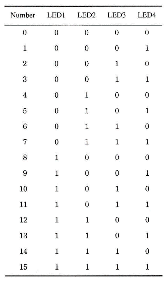
The numbers are given by four LEDs, each of which can represent 0 (off) and 1 (on). They can be on or off in any combination as shown in the table. When you press S, the LEDs will flash to produce random combinations. When S is released, the LEDs will remain in one of the combinations correspondent to the generated number. Unlike the previous project, this circuit does not have an "inertia" circuit that causes a delay in arriving at the generated number.
The circuit is powered from AA cells and can be used in basically the same experiments suggested for Project 38.
Experiments
■ The subject must guess what number will be generated. As suggested in the previous project, there are several ways to improve the tests. The LEDs can be
The circuit is sensitive enough to be triggered by some natural magnetic field changes (e.g., lightning strikes during a storm or even when a nearby electrical device is turned on). However, when used in field studies, distant from any source of interference and on a clear day (or night), a triggering event can be a strong signal that a UFO is nearby.
Experiments
■ This device is useful not only for UFO detection experiments. In ESP experiments, the circuit can detect whether any change in the ambient magnetic field is produced when a subject is in a trance state in experiencing ESP.
■ A subject can try to control or alter the ambient magnetic field using mental powers in PK experiments.
■ As in ESP experiments, the subject can try to control the ambient magnetic field in transcendental meditation experiments or for biofeedback.
How It Works
Any change in the ambient magnetic field produces a small voltage in the coil's terminals. This voltage is applied to the inputs of an operational amplifier (IC1). The voltage gain of this amplifier is determined by the feedback network formed by P1. The higher the resistance of this component, the higher the voltage gain of the circuit. The amplified voltage is then applied to the base of Q1, which forms a second amplification stage.
When this transistor is saturated with a signal coming from the previous stage, the trigger input of a 555 timer IC, wired as a monostable multivibrator, goes to the low logic level. At this moment, the monostable triggers, with its output going to the high logic level.
The output will remain in the high logic level even when the detected magnetic field changes disappear. The time span during which the output remains high de-pends on R5 and C2. The next stage, triggered by the monostable multivibrator, is a two-transistor audio oscillator. This oscillator drives a loudspeaker, and its frequency is deter-mined by R6 and C3. Power comes from four AA cells (6 V), and current drain is very low, extending battery life.
Assembly
Figure 1 shows a diagram of the UFO detector. The components are placed on a small printed-circuit board as shown in Fig. 2.
The coil is the critical component in this project. Sensitivity depends on the number of turns on the coil. The higher the number of turns, the more sensitive the device.

The reader has two possibilities to obtain this component. One is to wind 5,000 or more turns of any wire between 30 and 34 AWG on a ferrite rod (any size that can accept that many turns). The other is use the primary winding of any trans-former with a high-voltage or high-impedance transformer. The primary winding of a 117 Vac x 6 V (50 to 250 mA) transformer can be used as the pickup coil. You only have to take out the core, leaving only the form with the wire as shown in Fig. 3.
A ferrite rod is then placed in the core (you can glue it or hold it in place using paper or a plastic sponge to fill the empty space). Ferrite rods with diameters be-tween 0.8 and 1.2 cm, and lengths in the range of 10 to 20 cm, can be used.
The circuit can be installed into a small plastic or wooden box. The dimensions of the box basically depend on the size of the loudspeaker and the cell holder.
If the ferrite rod is too long to fit inside the box, make sure that both ends ex-tend outside the box.
On the front panel, we have two controls: the on/off switch and the sensitivity control. When mounting the circuit, observe the position of polarized components such as the transistors and the electrolytic capacitors.

Testing and Using the Circuit
Place the cells in the cell holder and turn on the power supply (close S1). Open P1 to put the unit in the higher gain condition.
Quickly pass a small magnet near the ferrite core. The circuit will be triggered, producing a tone for a few seconds.
You can change the tone by adjusting C1 or R6. The length of time that the tone is on is determined by R5. Values between 22 kΩ (for short tones) and 470 kΩ can be tested.
In use, place the device in any suitable location (i.e., at a distance from ac power lines or devices that can trigger it, such as cars, telephone lines, etc.) and turn it on. The production of any tone indicates the presence of a magnetic field change in that location.
Note: the circuit tends to be triggered by atmospheric electrical discharges such as lightning from an approaching storm.
Suggestions
■ You can increase the unit's sensitivity by adding a 10 M resistor in series with P1.
■ Fast changes in the magnetic field can become undetectable if a capacitor with values in the range between 1 and 10 µF is placed between the base of Q1 and the 0 V power line.
■ The tone produced by the oscillator can be adjusted by replacing C3 with one of a different value, between 0.01 and 0.1 µF.
■ A tone control for the signal can be added. Replace R6 with a 10 kΩ resistor and add a 100,000 Ω trimpot in series with this component.
■ A photo diode can replace the coil. In this configuration, the circuit will detect small changes in light intensity or light flashes in an ambient.
Semiconductors
IC1 CA3140 operational amplifier, integrated circuit
IC2 555 timer, integrated circuit
Q1, Q2 BC548 or equivalent general-purpose NPN silicon transistor
Q3 BC558 or equivalent general-purpose PNP silicon transistor
Resistors
R1, R5 100 kΩ-2, 1/8 W, 5%—brown, black yellow
R2 4.7 kΩ, 1/8 W, 5%—yellow, violet, red
R3 10 kΩ, 1/8 W, 5%—brown, black, orange
R4, R6 47 kΩ, 1/8 W, 5%—yellow, violet, orange
R7 1 kΩ, 1/8 W, 5%—brown, black, red
Capacitors
C1 0.47 µF, ceramic or metal film
C2 2.2 µF/16 WVDC, electrolytic
C3 0.047 µF, ceramic or metal film
C4 100 µF/12 WVDC, electrolytic
Miscellaneous
L1 Pickup coil (see text)
P1 4,700 kΩ potentiometer
SPKR 5 cm x 4/8 Q loudspeaker
S1 SPST, toggle or slide switch
B1 6 V, four AA cells
Printed circuit board, plastic or wooden box, cell holder, knob for P1, wires, solder, etc.


