Although the studies on the effects of electrical stimulation on the skin in the treatment of cellulite have not arrived at definitive conclusions yet, we can find in ads several equipments for this purpose, some quite simple and of personal use. We do not recommend the use of such equipment without a prior medical appointment, but if your doctor allows you, we can teach you how to build a simple stimulator. The shown circuit generates high voltage pulses which stimulate the skin at the cellulite site forcing the body to react and thus, it is claimed, so that a favorable physiological change occurs to the problem treatment.
Of course, the circuit should be used quite moderation and never without expert guidance. If the reader intends to industrialize the circuit, it is also important to note that there are no medical conclusions to ensure its full efficiency.
Note .: according to medical documentation that we obtained from various sources, the electrical stimulation appears to have effect on the muscles, acting on blood circulation and it has many additional effects however they are not definitely proven by medicine, thus there is no clinical evidence that the process is effective.
How it works
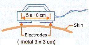
The basic idea of the circuit is to generate a high voltage of average frequency which can be applied to stimulation electrodes. This voltage can be adjusted between 0 and about 150 V to be able to find the ideal spot that is noticeable but not unpleasant. In Figure 1 we give an idea of how these electrodes can be built.

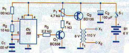
To ensure greater security in the application, the device is powered by standard batteries that will have a good durability in application. Then we have a low frequency oscillator, something around 500 Hz, designed around 555.
The rectangular signal of this oscillator is applied to a stage with two transistors which have an intensity control. The control doses the signal applied to a voltage elevator transformer. On the high voltage winding of the transformer have the signal which will be applied to the electrodes.
Assembly
In Figure 2 we have the complete diagram of the stimulator for the treatment of cellulite.

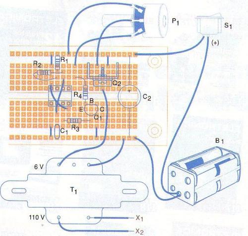
The assembly can be performed in a printed circuit board with a standard solderless board, as shown in Figure 3.

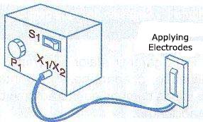
The transformer can be of any kind which has a primary winding of 110 V or 220 V and secondary of 6 V with currents between 250 mA and 500 mA. With a small transformer, the device fits in a plastic box, as shown in Figure 4.

The power transistor must be provided with a small heat radiator consisting of a small sheet of metal. The other components are not critical and for the potentiometer should be used a scale that better adjusts to the stimulus intensity .

For testing should be enough touching the electrodes on the skin and turn on the unit, initially with the potentiometer in the minimum intensity position.
Then start turning the potentiometer to get a slight tingle.
The application should be performed with this intensity on sessions of 10 to 20 minutes a day. An idea of the design improvement consists on replacing R1 for a resistor of 10 k Ω and connect it in series with a potentiometer of 1 M Ω to control the frequency.
Important: Never feed this circuit with a transformerless power supply.
CI-1-555 - CMOS integrated circuit
Q1 - BC558 or equivalent - PNP transistor for general use
Q2 - BD136 or equivalent - PNP transistor medium power
R1 - 100k Ω x 1/8 W - resistor - brown, black, yellow
R2 - 10 k Ω x 1/8 W - resistor - brown, black, orange
R3 - 2.2 k Ω x 1/8 W - resistor - red, red, red
R4 - 1k ohm x 1/8 W - resistor - brown, black, red
C1 - 100 nF - ceramic capacitor or polyester
C2 - 100 µF x 12 V - Electrolytic Capacitor
S1 - SPST switch
B1 - 6 V - 4 small batteries
P1 - 4.7 k Ω - linear potentiometer
T1 - primary transformer with 110 V or 220 V and 6 V secondary with 250 to 500 mA
X1, X2 - electrodes - see text
Miscellaneous:
Universal circuit board, battery support, mounting box, button pot, heatsink for Q2, wire, welding, etc..


