Low-frequency magnetic fields are thought to have beneficial effects in some situations involving health.
For example, it has been found that fracture recovery can be accelerated with the help of external magnetic fields.
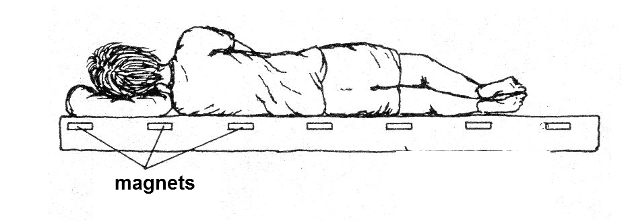
Aches, it is believed, can also be relieved under certain conditions with the help of low frequency fields and even the presence of permanent magnets, as suggested in Figure 1.
However, there are also studies which show that intense fields can be harmful to health like those created by power transmission lines.
So, our project does not promise any effect, because this is on behalf of each individual.
We only teach how to assemble a small generator of small intensity magnetic fields which can be applied to small regions of one’s body for the purposes discussed above.
The field is of low intensity, offering no danger and the handling of the device is simple and safe.
HOW IT WORKS
When an electric current flows through a coil, as shown in Figure 2, a magnetic field is created.
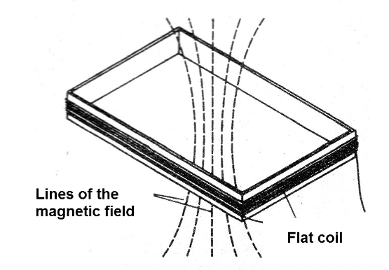
The intensity of this field will depend on the intensity of the current and also on the number of windings of the coil.
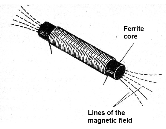
Thus, to create a low-frequency magnetic field, what we do is to use an oscillator and an amplifier that apply the signal to a small coil, as shown in Figure 3.
This circuit can also be used in experiments in the biology or botanical laboratory to study the effect of fields on animals.
ASSEMBLY
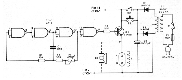
In Figure 4 we have the complete circuit of the device that makes use of a CMOS integrated circuit as an oscillator.
For a trial version, the circuit may be built on a protobard array with the array of components shown in Figure 5.
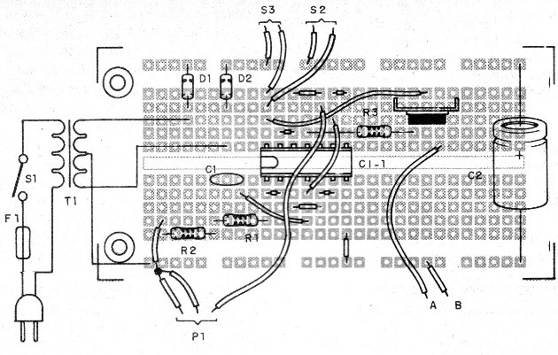
In the assembly, observe the position of the integrated circuit and the transistor.
In this version, we supply power from a source, but nothing prevents medium or large batteries from being used, since the consumption of the circuit is rather high.
The transformer has a secondary current of approximately 500 mA.
In Figure 6 we have a suggestion of a box for the assembly.
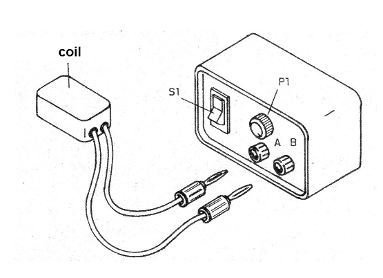
The coil is of homemade construction and can be winded into a small form of a cardboard or box ith the dimensions shown in Figure 7.
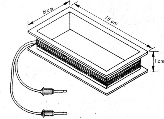
This coil consists of 30 to 100 turns of enamelled wire that can have any thickness between 28 and 32 AWG.
A cable with plugs is used to connect the coil to the device.
TEST AND USE
To test, simply turn on the unit and approach the coil of an AM radio tuned out of station.
If the circuit is operating, interference must be detected.
We can also test the circuit by connecting its output to a piezoelectric transducer or even a small speaker which should beep.
S2 switches a speaker just in order to check the operation.
S3 is used for momentary applications by activating the device for short time intervals.
To use, simply position the coil on the place where you want to apply the magnetic field.
CI-1 - 4011 - CMOS integrated circuit
Q1 - TIP110 - Darlington power transistor
D1, D2 - 1N4002 - silicon diodes
S1, S2 - Single switches
S3 - Pressure switch
F1 - 500 mA fuse
T1 - Transformer - see text
T - coil
C1 - 2n2 - ceramic or polyester capacitor
C2 - 1000 uF x 12 V - electrolytic capacitor
R1 to R3 - 10 k ohm x 1/8 W - resistors - brown, black, orange
P1 - 470 k ohm - potentiometer
Miscellaneous:
Printed circuit board or contact array, power cable, coil material, wires, welding, etc.


