The idea is that the sense of touch is transmit from an artificial hand to transducers installed in glove or even on a flat surface where a person’s hand is placed, as shown in Figure 1.
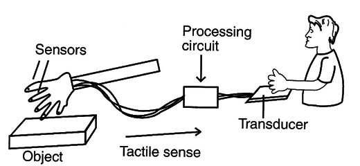
The first question to be asked is, what kind of electric magnitude should we choose to transfer to a person's fingers as a tactile sensation: vibration, electric shock, mechanical pressure, or temperature?
The idea explored in this project is vibration, because it is an electric magnitude that is easy to work with using simple circuits.
Thus, our project will transmit the sensation of vibration using small transducers.
The idea of a remote, sensing tactile organ is very interesting and can be used for a Variety of different purposes. For instance, a bionic tactile organ can be installed in an artificial hand, as shown in Figure 2.
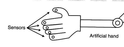
The project is safe because it ís powered by cells and is easy to mount in the basic version.
Applications
An artificial tactile organ can be used with an artificial hand or arm and in many other applications. The reader can create a robot able to send tactile information to the operator.
For instance, this robot will be able to handle objects with precision, sensing the pressure necessary to pick up and place an egg without breaking it.
Create a bionic hand With tactile sense.
Desígn a remote sensing device for general use.
Demonstrate how senses can be converted into electric signals.
How it Works
The circuit ís formed by many oscillators (one for each finger) with a frequency determined by the amount of pressure on an electrode.
The simplest electrode is made with conductive form, which is also used to protect integrated circuits (ICs) from an electrostatic discharge (ESD). Figure 3 shows how this foam is used
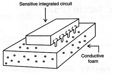
When the foam is pressed, its ohmíc resistance falls, changing the frequency of the oscillator. The basic frequency is determined by C1, the resistance of X1 (the sensor), and R1. The circuit is calculated to produce a central frequency in the audible range, something around 1 kHz.
In this project, we will use a 555 IC for each oscillator, but other ICs can be configured for the same task, as we will suggest at the end of the article.
The output of this circuit is powerful enough to drive a transducer, which will be the interface between the sensors and the fingers of the operator.
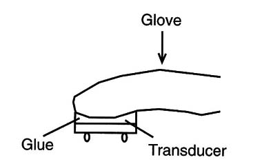
Small piezoelectric transducers can be used for this task, and they can be installed inside a glove or, if the reader prefers, on a surface where the fingers can be placed.
The circuit is powered from common AA cells. The current drain is Very low and four cells can power all five circuits necessary for each finger of a hand. Details of the construction are given in the following section.
How to Build
Figure 4 shows the schematic diagram of one oscillator. The reader will mount five circuits like this to transmit the tactile sense to each finger.
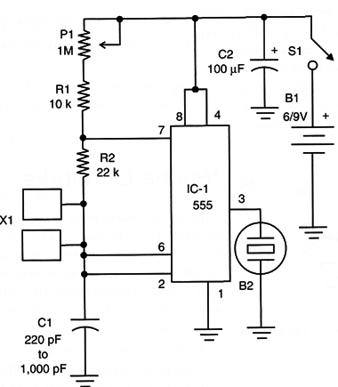
The circuit can be mounted on a solderless board or a printed circuit board (PCB), such as the one shown in Figure 5.
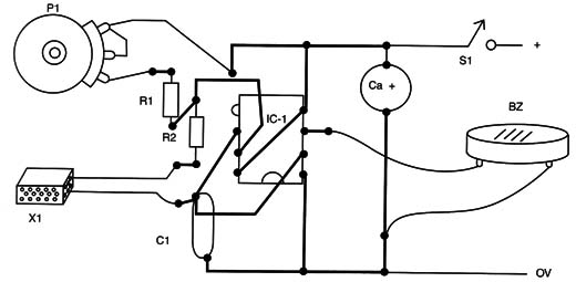
P1 adjusts the frequency according to the characteristics of the sensor. C1 can be tested using a large range of values between 220 pF and 1 nF. The ideal value is one that matches the resistance of the sensor providing an audible tone.
P2 adjusts the level of excitation or sensitivity in the sensor. Low levels are better because they fall in a range where our tactile sensors are most sensitive.
The circuit can be housed in a small plastic box. If many oscillators are used, cables should be used to connect them to the remote hand. All the oscillators can be powered from the same power supply.
Do not use power supplies from the AC line because they are dangerous in an application where hands or body parts have contact with devices in the circuit
The Sensors
Figure 6 shows how the sensors can be mounted on an experimental bionic finger or hand.
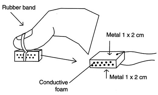
Small pieces of conductive foam are cut and placed between the electrodes, which are formed by flexible metal plates or grids. Find a foam soft enough to be easily compressed under pressure.
The transducer can be mounted inside a glove, as shown ín Figure 7.
Another solution is to mount the transducer on a flat surface, such as a piece of wood, where the subject can place his or her hand, as shown in Figure 8.
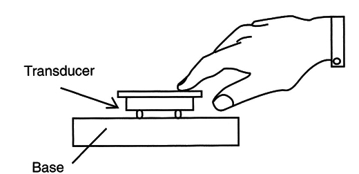
One must be able to touch the vibrating mem-brane or even the piezoelectric crystal.
Testing and Using
Power the circuit on and place your finger on the transducer. Adjust P1 until you sense a light vibration. Then, pressing the sensor, the vibration wíll change, giving more tactile sensation or vibration.
The amount of Vibration is proportional to the pressure in the transducer.
When usíng the glove device, you will touch the objects With the sensors and try to determine shape and consistency from the vibrations in your fingers.
Of course, how well you determine those characteristics will depend on the number of sensors used in the hand.
Suggestions
A bionic tactile device has many functions and is limited only by the imagination of the evil genius. You can work with different types of sensors and use different techniques for transmitting the sensations to a person’s fingers or a receiver.
Some suggestions for upgrading or creating new solutions are given in the following section.
Using Other Transducers
The first idea to explore is the use of a small loudspeaker as a transducer in the output stage. As shown in Figure 9, a person touches the loudspeaker, which will need drivers that use transistors.
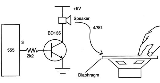
The loudspeaker produces a mechanical vibration that can be sensed by the fingers.
Small electromagnets with a metal diaphragm can also be used, as shown in Figure 10.
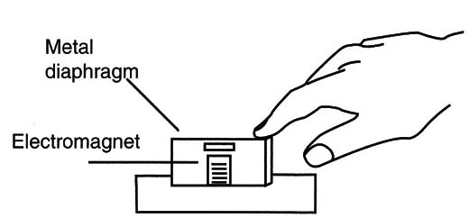
The electromagnet are formed by 100 to 500 turns of 30 to 32 AWG wire around a small screw.
Circuit Using the 4093
Figure 11 shows how a 4093 IC can be used as a pressure-controlled oscillator suitable for this application.
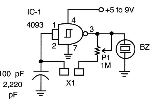
The advantage of this configuration is that you can use only one IC to drive four transducers from the signals picked up by three sensors.
Working with Electric Stimulation
Another interesting project using a tactile transducer is shown in Figure 12.
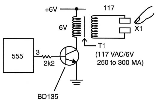
The circuit applies electric shocks to one’s fingers from the stimulus picked up by the sensors.
P1 is adjusted to put the circuit in the threshold of stimulation; that is, Where the vibrations begin to be sensed. Then any change in pressure will lower the frequency, increasing the voltage applied to the sensor.
The central frequency of the oscillator must be found to provide the best sensation of pressure in the receiver.
IC-1: 555 integrated circuit timer
S1: On/off switch
B1: 6 V source or four AA cells
BZ: Piezoelectric transducer
X1: Pressure sensor (see text)
P1: 1 MΩ potentiometer
R1: 10 Ω x 1/8 W resistor brown, black, orange
R2: 22 Ω x 1/8 W resistor red, red, orange
C1: 220 pF to 1,000 pF ceramic capacitor
C2: 100 µF x 12 V electrolytic capacitor
Other:
PCB, cell holder, plastic box, wires, solder, etc.


