Note: this article is based in a collection of projects published by the author in many magazines and gathered to be included in the book Bionics For The Evil Genius, published in USA in 2006.
Of course, experiments can be made to see how the same sounds can affect other living beings, such as fish in an aquarium.
Using an audio oscillator, it is possible to scare insects away from certain areas such as a bedroom or, when camping, a tent. This project serves as an interesting application of bionics where an electronic circuit imitates a living being interacting with the insects.
The circuit can also be used to study the habits of insects and how external influences (such as sounds) can alter them.
The basic version of the project consists of a simple audio oscillator driving a small piezoelectric transducer. Other versions using high-power circuits will be given too (such versions can be bought in camping stores).
The circuit can be used either in scientific works or in practical applications.
Because the current drain will be very low, the circuit can be powered from AA cells, a 9-volt battery, or even a power supply plugged into the AC power line. The low current drain will allow the battery life to last a number of weeks.
An adjusting potentiometer is also included that acts on the frequency, which ranges from 200 to 2,000 Hz typically. However, depending on the application frequency, the range can be altered by replacing C1. Values between 2,200 pF and 0.1 µF can be tested.
It is also possible to replace the transducer, making the circuit oscillate in the supersound range.
Bionics Experiments and Applications
The tone produced is strong enough to allow this circuit to be used in experiments involving bionics and even some practical applications such as those shown in the following sections.
Fish Attractor
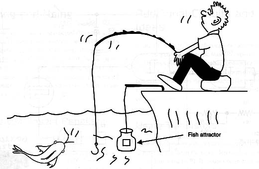
A circuit can be created to produce a sound that imitates an insect in the water trying to escape, which attracts fish. This effect is used in commercial fish attractors, and it is only necessary to install the circuit inside a bottle, as shown in Figure 1.

The weighty metal piece is necessary to make the bottle dive into the water.
The reader must find the ideal frequency to attract the desired fish, and experiments made in an aquarium can be performed to study the habits of the fish.
Repelling Other Insects:
Experiments can be made to see if the circuit can be used to scare insects such as ants and cockroaches.
The reader will have to change the capacitor and the resistor in the frequency circuit to find the ideal tone for the application.
Effects on Plants:
Experiments to verify if the tones have an effect on plant growth can be performed as well.
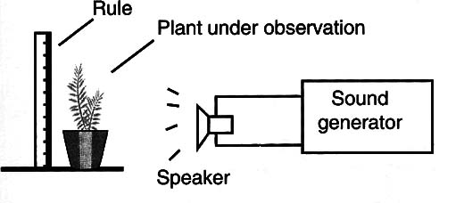
Simply place the circuit near the plant under observation, as shown in Figure 2.

Because the current drain of the circuit is very low.common AA cells can be used to power the circuit over many weeks. Of course, for even longer experiments or applications, the circuit can be powered from a 3-voltAC/DC converter.
Any type of power supply with currents in the range of 50 to 250 milliamps is suitable for this application.
When wiring the power supply to the circuit, be sure to observe the polarity of the connector. Don’t use transformerless power supplies for safety reasons.
In the next section, we will see how a power stage can be added to increase the sound volume.
How the Circuit Works
The circuit is made from a 4093 complementary metal oxide semiconductor (CMOS) integrated circuit (IC), which consists of four Schmitt NAND gates. One of the four gates is wired as an audio oscillator, driving the three other gates that work as a digital buffer or amplifier.
The frequency is determined by C1 and can be adjusted to a large range of frequencies by P1. C1 can be changed if the frequency range covered by the circuit is not large enough for the application the reader has in mind.
The signal from the output of the circuit is square and can be used to directly drive a high-impedance piezoelectric buzzer. Do not use loudspeakers or a low-impedance transducer directly plugged into the output of the circuit. Using this kind of transducer will be discussed later.
How to Build
Figure 3 shows the schematic form of the insect repellent.

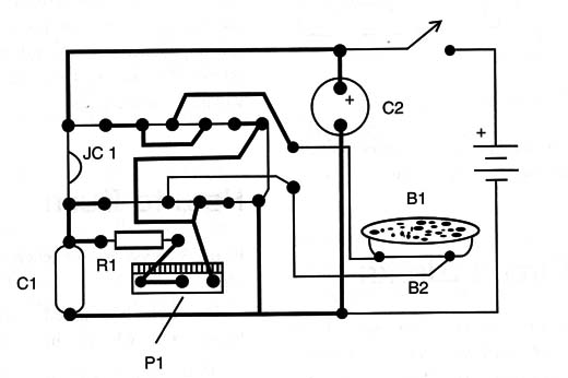
This circuit is mounted on a small printed circuit board (PCB), which is shown in Figure 4.

All the components can be housed into a small plastic box. Holes should be drilled into the box to allow the release of the sound produced by the transducer.
The transducer is a piezoelectric type, such as the ones used in buzzers, but you can also experiment with transducers from ceramic mikes or phones.
Testing and Using
Turn on the power switch and adjust P1 to the desired audio tone. The ideal tone can be obtained by experimenting, and in a general sense, the perfect tone will be the one that is closest to the sound produced by the actual insect.
Experiments shows that certain female insects do not tolerate the presence of other females, so reproducing their sound will probably lead to repelling them.
IC1: 4093 CMOS integrated circuit
Bz: Piezoelectric transducer (see text)
R1: 10,000 ohm (10 k ohm) 1/4-watt, 5 percent resistor, brown, black, orange
P1: 100,000 ohm (100 k ohm) potentiometer
C1: 0.015 µF ceramic or metal film capacitor
C2: 10 µF/12 WVDC electrolytic capacitor
S1: SPST toggle or slide switch
B1: A 6 or 9 V source or four AA cells or 9 V battery
Other parts: PCB, cell holder or battery connector, wires, plastic
box, solder, etc.


