Obs. This article was originally written in Portuguese and translated into English to be included in my book Bionics for the Evil Genius (TAB2006).
Oscilloscopes are useful tools for viewing these signals, but they are very expensive instruments, and normally the common bionics evil genius doesn’t have one at his or her lab.
Another tool for detecting signals produced by living beings uses a high gain amplifier, such as the one that will be described here. It is cheaper and can be built using a few common parts, all of which can be found at your nearest electronic component dealer.
Signals produced by the metabolism of plants, insects, fish, and even humans can be amplified to drive an indicator. In this project, the indicator is a moving coil galvanometer in order to keep the cost of the device low.
The circuit is very safe because it is not plugged into the AC power line. It can be powered from common cells or a battery, presenting a very low current drain and a very low input impedance. This is a very important characteristic if you doxnot have much electronics experience and intendxto detect signals generated by your own body.
The project consists of a high-gain operational amplifier with an external gain control.
The circuit can be used to detect very weak signals ranging between 10 microvolts and 1 volt. Remember that the nerve cells (the neurons) of a human generate pulses between 10 and 50 millivolts.
Because of the very high input impedance (many teraΩ, or thousands or billions of Ω), it is important to not load the circuit when testing, and keep in mind that living beings are normally high-impedance sources of signals. A large number of projects and experiments in bionics can be performed using this amplifier.
Experiments in Bionics
The low voltage generated by living beings can be used to drive many electronic circuits or be observed to learn more about the way the voltages are produced. Experiments can be performed to see how these voltages change when the specimens are placed under special conditions (the influence of light, magnetic fields, chemical substances, etc.).
The following list of experiments and applications is not a complete one, but the reader, using his or her imagination, can add many others:
Detect voltages generated by plants. The Backster effect” can be studied using a bio-amplifier.
Detect changes in the resistance of skin, using the amplifier as a lie detector or in experiments to detect stress.
Observe changes in the electric potential of electrodes immersed in an aquarium due to the presence of fish or other beings.
Detect voltages produced in biological processes such as fermentation or putrefaction.
Cleve Backster has conducted hundreds of experiments showing that plants respond to our emotions and intents, as do severed or crushed leaves, eggs (fertilized or not), yogurt, scrapings from the roof of a person’s mouth, sperm, and so on. Backster’s claims were refuted, however, by Horowitz, Lewis, and Gasteiger (1975) and Kmetz (1977). Kmetz denied Backster’s ideas in an article for the Skeptical Inquirer in 1978. He said that Backster had not used proper controls in his experiments.
When controls were used, no detection of the plant’s reaction to thoughts or threats could be found. They also said that the cause of the polygraph contours could have been due to a number of factors, such as static electricity, movement in the room, and changes in light and humidity.
For our readers who need to see to ‘Cleve Backster published some research in the International Journal of Parapsychology (“Evidence of a Primary Perception in Plant Life”, vol. 10, no. 4, Winter 1968, pp. 329-348). He tested his plants using a polygraph machine and found that plants react to thoughts and threats.
Believe or not, why not try the experiments? To learn more about the subject, we recommend the book The Secret Life of Plants by Peter Tompkins and Christopher Bird.
How irt Works
The voltages generated by biologic processes are very low, on the scale of few millivolts, and the impedance of the source is very high. This means that the total power involved in the processes is very low, needing high gain amplifiers to be used in any application, such as driving a meter.
The ideal device for the amplification of very low voltage signals is an operational amplifier (see Figure 1).
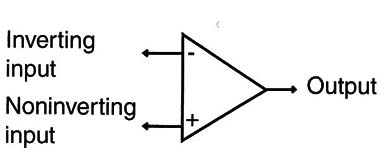
An operational amplifier has a very high input impedance, a large voltage gain, and a low impedance output.
The amplifier has two inputs, an inverting input and a noninverting input. The output is a single line and the gain is fixed by the feedback resistor R2. The ratio between R2 and R1 determines the gain of the amplifier.
A common operational amplifier can be programmed to have gains between 1 and more than 100,000 times the signal, which necessitates replacing R2 with a potentiometer, as we are going to adopt in our project. Common operational amplifiers also have an input impedance of some megΩ, but a special type of operational amplifier has very high input impedance, in the range of many teraΩ.
They use field-effect transistors (FETs) or junction field-effect transistors (J FETs).
High input impedance is very important in applications involving biological systems because it doesn’t load the source. This means that the presence of the external amplifier causes a minimum of influence in the system to be studied, as indicated by Figure 2.
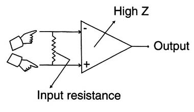
Loading the source occurs if a something attached to the circuit drains more current than is provided at the output of the circuit. For instance, if a 100 mA load is connected to the output of an amplifier with a maximum current of 50 mA, the amplifier will be loaded.
The basis of our circuit is the CA3140, a common JFET operational amplifier with an input impedance of many teraΩ. The gain is programmed by a feedback resistor and is selected by a switch. In the high gain position, the circuit can present a gain of 100,000. The current drain is very low, so the cells can have their life extended for several weeks or even months.
The operation of the circuit is in the differential mode, meaning that the circuit amplifies the difference of the voltages applied to the inputs. This means that the output of the circuit when the voltage between the inputs is zero is half the power supply voltage. As the input 1 goes positive or negative when compared to input 2, the output voltage oscillates to more or less than Vcc/2 (half the power supply voltage).
Special care must be taken when connecting the inputs to a specimen. High impedance input also means sensitivity to noise. The wires must be short and shielded, and operation must be far from noise sources such as fluorescent lamps, transformers, and so on.
How to Mount
Figure 3 shows the complete diagram of the basic version for the bio-amplifier.
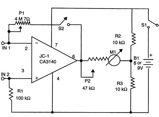
The reader can mount it using many common processes, but printed circuit boards (PCBs) and solderless boards are the best.
Figure 4 shows how to mount the circuit using a small PCB.
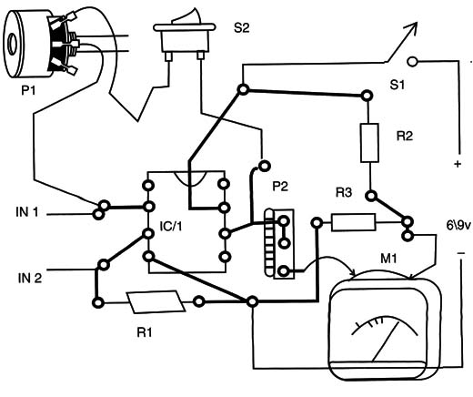
The components are housed inside a small plastic box, having as external controls the gain switch and the on/off switch, as shown in Figure 5.
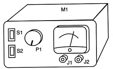
Any galvanometer with full-scale currents between 50 and 200 µA can be used. A multimeter (analog or digital) can also be used, replacing the analog galvanometer.
The electrodes depend on the application. To plug the electrodes into the circuit, plastic terminals can be used. Different colors are used to indicate the inverting (-) and noninverting (+) inputs of the circuit.
When handling the operational amplifier, avoid touching its terminals. The JFETs are very sensitive to electrostatic discharges (ESD). If your body is charged and you touch the component, you can burn it.
Testing and Using
Place the power supply (cells or battery) in the circuit and turn on S1. Keep S2 closed for initial tests and open P1, adjusting this potentiometer to the highest resistance.
Touching the input terminals, adjust P2 to have visible indications that do not pass the end of the scale. Now open S2 and repeat the tests. The indicator will move even when you place your hand close to the input terminals without touching them.
The bio-amplifier can be used in two basic ways: as a voltage monitor or as a resistance monitor. When using the circuit as a voltage monitor, the signals generated by the specimen are amplified. The specimen acts as a voltage source or a generator, producing a direct current (DC) or an alternating signal (AC).
Figure 6 shows how to place electrodes on a plant to observe the voltage generated by its biological activities.
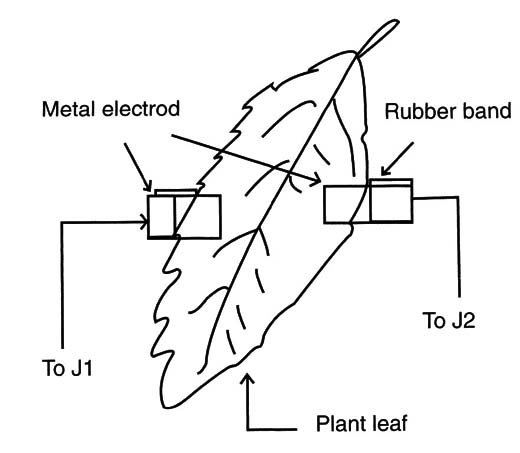
The electrodes can be made by small metal plates.
Use nonoxidable materials because the galvanic action of the plant fluids can attack the electrodes, granting undesirable voltages and altering the indications. This galvanic effect can also kill the tissue where the electrode is placed in a few hours after the experiment has begun.
When using the bio-amplifier as a resistance monitor, the circuit will detect changes in the resistance of a specimen, as shown in Figure 7.
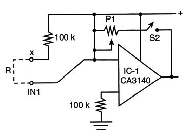
P1 and the resistance of a specimen act as bridge or voltage divider. Adjust P1 to get half the voltage of the power supply and then any change in the resistance will be amplified and shown by the instrument plugged into the output of the circuit.
IC-1 - CA3140 integrated circuit and JFET Operational amplifier
P1: 4.7 M ohm lin or log potentiometer
P2: 47 k ohm trimmer potentiometer
R1: 100 k ohm x 1/8 W resistor, brown, black, yellow
R2, R3: 10 k ohm x 1/8 W resistors, brown, black, orange
S1, S2: On/off switch
B1: A 6 or 9 V source or four AA cells and holder
M1: 0-50 µA to 0-200 µA galvanometer
Other: PCB or solderless board, cell holder or battery connector, wires, solder, electrodes.


