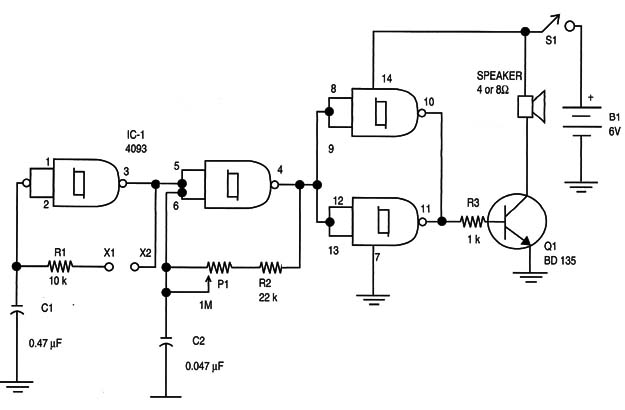
Note: this circuit was originally published in a Brazilian Magazine and translated into English to be part of my book Bionics for The Evil Genius (TAB 2006).

The loudspeaker Will produce bips at a rate that is dependent on the pressure exerted on the electrodes.
Figure 2 shows the wave shapes in different conditions of operation for the circuit.

The circuit uses the 4093 IC as its base, as in the original basic version, but in this configuration two gates are used as oscillators. One of them has its frequency dependent of the resistance between the electrodes X1 and X2, that is, the resistance of the skin of the subject if it is a person.
This oscillator, running at a very low frequency (between 0.1 and 5 Hz), controls a second oscillator running also at a low frequency but a little higher, between 500 and 1,000 Hz.
The result is an intermittent signal, applied to the base of a medium-power NPN transistor. This transistor has the loudspeaker as its load.
The sound is loud depending on the power supply voltage and loudspeaker.
Power that ranges from 200 milliwatts (mW) to 1 watt will be produced from the supply. As in the previous versions found in this section of the site, do not power the circuit from transformerless power supplies.
The circuit can be mounted on a PCB or solderless board. Q1 must be mounted on a heatsink.
If you want to supply more power to the sound, power the circuit from a 12-volt supply and replace Q1 by a TIP31.
Power the circuit on and place your fingers on the electrodes. The electrodes must be separated, but you must touch them at the same time. The sound will change as long you press and release your fingers, changing the pressure on the electrodes.
The frequency of both the tone and the intermittence can be changed by replacing C1 and C2. Try experimenting with these components according to the applications.
A sensitivity control can also be added. It is a 4.7 M ohm potentiometer between pin 1 and 2 of the IC and the O-volt line. The electrodes are the same as those described in the basic project (BM008).
ICI: 4093 CMOS integrated circuit
Q1: BD135 NPN medium-power silicon transistor
R1: 10 k ohm x: 1/8 W resistor, brown, black, orange
R2: 22 k ohm x 1/8 W resistor, red, red, orange
R3: 1 k ohm x 1/8 W resistor, brown, black, red
P1: 1 M ohm potentiometer, lin or log
C1: 0.47 µF or 1 µF polyester or electrolytic capacitor
C2: 0.047 µF x 12 V polyester or electrolytic capacitor


