Note: this article was originally published in Brazil, and them translated and adapted to be Evil Genius (TAB – 2006).
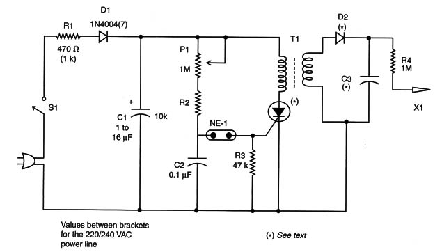
The circuit in Figure 1 is an ionizer powered from the AC power line. The values between the brackets in the parts list are for the 220/240 VAC power line.

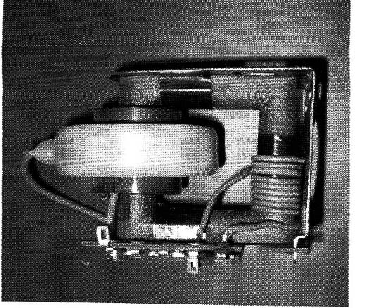
The circuit consists of a relaxation oscillator driving a flyback transformer, such as one found in an old TV set or video monitor. Find one with part of the ferrite core exposed to make the primary Winding, as shown by Figure 2.

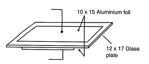
The primary is formed by 7 to 15 turns of common covered wire 22 or 24 AWG. The circuit can be mounted on a terminal strip or a PCB and is housed in a plastic box. C3 is a glass capacitor mounted as shown in Figure 3.

Replace the 1N4004 with a 1N4007 and the TIC106B with a TIC106D when plugging the device into a 220/240 AC power line.
The size of the glass piece is not critical. Aluminum foil or copper foil can be used as armatures for this capacitor.
C1 determines the power of the circuit, and values between 1 and 16 µF can be used. A high-voltage capacitor can be salvaged from old TV sets, but before using it, test it because this kind of component will suffer from loss capacitance if it hasn't been used for a long time interval.
The SCR doesn’t need a heatsink, because it conducts for short intervals of time without dissipating large amounts of heat. The only component that heats a little is R1, so you should mount it leaving 1 or 2 millimeters of separation from the PCB.
D2 is any high-voltage rectifier, Which can also be found in old TV sets. It is usually connected to the flyback. Also, When using this ionizer, take care to not touch the electrode.
SCR: TIC106B (D) SCR
D1: 1N4004 (7) silicon rectifier diode
D2: High-voltage rectifier, 15 kV or more
NE-1: NE-2H or equivalent neon lamp
R1: 470 ohm (1 k ohm) x 10 W wire-wound resistor
R2: 10 k ohm,x 1/8 W resistor, brown, black, orange
R3: 47 k ohm,x 1/8 W resistor, yellow, violet, orange
R4: 1 M ohm x 1/8 W resistor, brown, black, green
P1: 1 M ohm lin or log potentiometer
C1: 1 to 16 µF x 200 V (400 V) electrolytic capacitor
C2: Glass capacitor – see text
S1 – On/Off switch
T1 – Flyback transformer (see text)
X1 – Electrode (as in project 040E)
Other: Power cord, PCB or terminal strip, plastic box, wires, solder, etc.


