Deccupling capacitors must be included wherever current or voltage spikes could be present and compromise the stability of the circuit. Some circuit locations are particularly well suited for these capacitors.
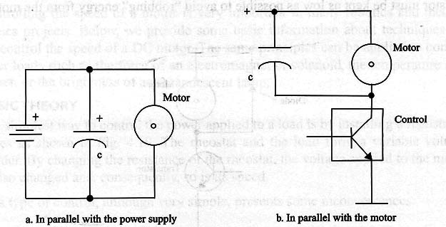
In parallel With the power supply. Large electrolytic capacitors should be added in parallel with the power supply as shown by Fig. 1.

These capacitors and add stored energy to the current supplied by the source when the motor is switched on and momentarily draws high current.
Values between 1,000 and 10,000 µF are suitable for common applications.
If the motors draw very high currents when switched on, and a drop in the supply voltage can’t be avoided, it is best to use a separate battery for each motor.
ln parallel with the motor. Capacitors in the range between 0.1 and 1 HP (polyester types) are recommended for absorbing the spikes generated by the motor’s commutation system. These capacitors will protect the switching devices against high-voltage spikes that are produced when the motor is running.
Protecting the Transistors
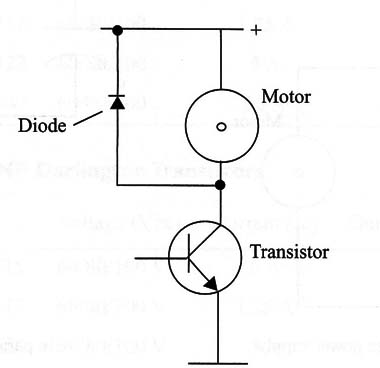
Transistors are very sensitive to voltage spikes that travel across them; e. g., spikes generated by inductive loads. Many types of transistors used for switching include internal protective diodes. If the transistors that you use do not have them, it is recommended that you add protection as shown in Fig. 2.

The ideal devices for this purpose are Schottky diodes, since these devices switch quickly enough to deal with the short pulses generated by DC motors.
But, for common applications, your circuits can be protected with common diodes such as the 1N4002 and others in the same series.
Current Sensing
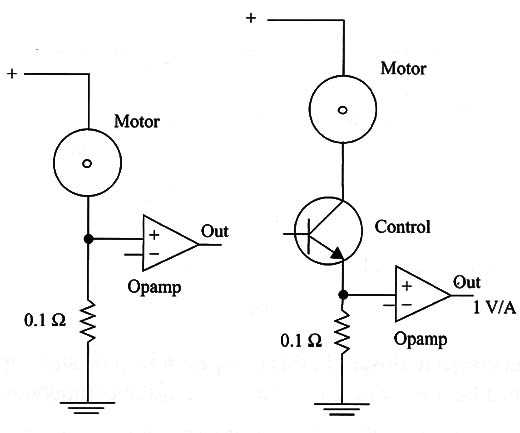
In some applications, it is important to add a circuit to monitor the current drain of a motor. This circuit can be used to control speed or manage power use to extend battery life. Figure 3 shows how this circuit can be added.

A 0.1 ohm resistor causes a voltage drop of 100 mV for each ampere drawn by a motor. Adding an operational amplifier with a gain of 10, for instance, you obtain 1 V/A directly driving some control circuit or monitor circuit. The value of the resistor must be kept as low as possible to avoid “robbing” energy from the motor.
Fuses
Many blocks projects controlling motors have “forbidden states” that can cause a power supply short out. The high current that would pass across the transistors in such conditions could burn them out.
To protect the circuit, fuses are recommended. The fuses are placed in series with the power supply, and their values depend on the motors and the transistors. It is a good rule of thumb to use fuse values 2.5 to 3 times greater than the normal current drawn by the motors.


