Even though advancements in manufacturing technologies have resulted in lower costs, these motors still are not very popular. It is likely that, within a few years, piezoelectric motors will become as popular as the more familiar types.
Some applications for piezoelectric motors are as follows:
1. Micropositioning stages
2. Manufacturing process control
3. Fiber optic positioning
4. Camera autofocus mechanisms
5. Computer disk drives
6. Robotic positioning
HOW THEY WORK
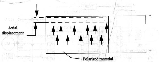
Piezoelectric materials generate an electric field When stressed along a primary axis. Conversely, the material changes its shape if a voltage is applied along this axis.
A common piezoelectric material is lead zirconate titanate. This type of ceramic material, as shown in Fig. 1, can be polarized by high-voltage electric fields.

Once the domains are properly aligned, the piezoelectric material can do useful work.
Piezoelectric motors use a polar ceramic shape to create motion through the use of periodic (sinusoidal) electric fields.
The typical piezoelectric characteristic of a ceramic material is 500 ppm/V (parts per million per volt), meaning a displacement of only 0.1 microns if 200 V is applied.
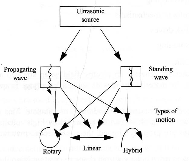
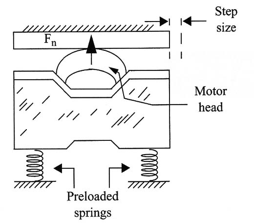
Piezoelectric motors can be classified as standing-wave (a single Vibration driving source) or propagating-wave (two standing waves with a phase shift of 90º) types. Figure 2 shows the main types of piezoelectric motors. The basic construction of a piezoelectric motor is shown in Fig. 3.


The force along the wear strip is about 2 to 3 N. The force can be calculated by the following equations.
Formulas:
V= Vo x< sin (ω .t)
and
F = υ xFn
Where
Vo = the original peak voltage (V)
f = the frequency (Hz)
t = the time (3)
F = the kinetic force (N)
υ = the coeficient of sliding friction
ω =2 x π x f
F = the normal force (N)


