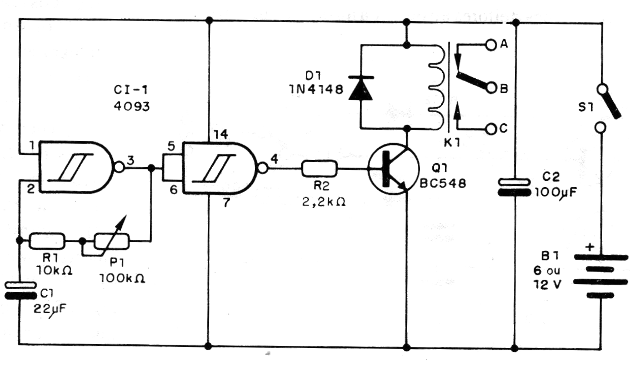
The circuit can be powered with voltages of 6 or 12 V and the power of the load as well as its supply voltage depend exclusively on the type of relay used in the design.
Among the possible applications for the device we mention the following:
- Intermittent to control signaling lamps
- Actuation of ventilation or cooling system motors
- Actuation of heating systems in the medium power regime.
CHARACTERISTICS
Supply voltage: 6 or 12 V
Maximum load current: 6 A
Load voltage: 6 to 220 V
Operating frequency range: 0.001 Hz to 1.5 Hz
The base of the project is an oscillator made around one of the four trigger NAND ports on a 4093 type CMOS integrated circuit.
With only two external components, as shown in Figure 1, we can build a rectangular oscillator with approximately 50% active cycle.

Using the variable resistor we can have a control over a wide range of frequencies. The oscillator in question controls an inverter buffer built around another NAND port and this, on the other hand, controls a transistor that triggers the relay.
The final result is a fairly simple and efficient configuration with low cost components.
The assembly is at the discretion of the reader, and may be on a printed circuit board or matrix of contacts.
The integrated circuit can be built on a socket, to avoid heat in the welding process.
The capacitor C1, which determines the periods of the actuation cycles, has values that can be chosen according to the following approximate table, since we must take into account the tolerances of the components.
| Frequency or operation cycles | C1 |
| 0.2 to 5 seg | 22 uF |
| 2 to 50 seg | 220 uF |
| 8 seg to 3 min | 1,000 uF |
We do not recommend the use of capacitors greater than 1000 uF, given the possibility of leakage that would affect the operation of the circuit.
For longer periods it will be preferable to increase P1 to values up to 1 M ohms, in which case we can get close to half an hour as the maximum operating cycle for the system.
Potentiometer P1 is linear or log and even higher values such as 220 k ohms or even 470 k ohms can be used.
The C1 capacitor must be of good quality, as leaks can compromise the proper functioning of the device.
To test, simply turn on the power and set P1. The opening and closing states of the relay contacts will help the reader check the operation.
We suggest using a higher frequency for this test.
The power can be provided by ordinary batteries or the power grid.
The consumption will be greater only at the moments in which the relay is with the contacts closed, since, with the open contacts the required current is of the order of 0.5 mA.
Cl-1 - 4093
D1 -1N4148
Q1 - BC548 or equivalent
K1 - relay - see text
Capacitors: 16 V
C1 - 22 uF - electrolytic
C2 - 100 uF - electrolytic
S1 - Single switch
B1 - 6 or 12 V - batteries, power supply or battery
P1 - 100 M ohms - lin or log potentiometer
Resistors: 1/8 W
R1 - 100 k ohm
R2 - 2.2 k ohm


