A tachometer in a car measures the acceleration of the engine which is not actually the acceleration (speed variation) of the vehicle itself. Once in gear, the change in speed will depend on the weight of the vehicle and eventually on whether or not it is on a flat road.
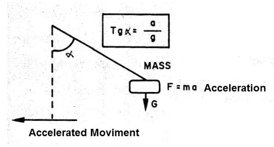
The measure of acceleration can be made in a simple way with a pendulum as shown in Figure 1, where the slope of the wire determines the force acting on the body at the change of the speed, which we know it corresponds to the acceleration.

For a 45 degree angle, for example, we have an acceleration imprinted on the vehicle equals to that of gravity.
A simple way to measure the acceleration of a vehicle would be to couple a pendulum to a potentiometer in order to convert the angle it deflects into voltage, and then apply this voltage to any indicator like an LED indicator in our design.
Of course, for a stationary vehicle, an indication of the position of the pendulum other than zero means an inclination of the ground.
The circuit is quite simple to assemble and can be easily adapted to any vehicle.
Characteristics:
Supply voltage: 12 V
Consumption: 20 mA
Number of LEDs: 5
HOW IT WORKS
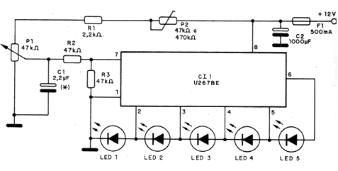
The basis of this project is a 5-LED mobile bar indicator of type U267BE of SID Microelectronics (see note at the beginning of the article), which barely requires external elements other than the signal splitter network and a power filter capacitor.
Containing all the elements to trigger the constant current LEDs, this component ensures uniform brightness for the scale and can work with the available 12V power from a car battery.
In our design, a potentiometer is the sensor. Coupled to a pendulum it transforms position variations into voltage variations.
The trimpot (P2) connected in series to the sensor (P1) allows adjusting the limits of the scale so that we have a range of operation at an angle smaller than that covered by the rotation of the potentiometer axis.
The capacitor C1 provides a certain inertia to the circuit, preventing the LEDs from flickering when the pendulum eventually oscillates in the presence of ground irregularities. This capacitor can be changed, depending on the desired effect. Its values can be between 2.2 uF and 220 uF.
ASSEMBLY
In Figure 2 we have the complete diagram of the apparatus.

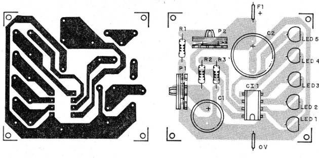
In Figure 3 we have the arrangement of the components on a printed circuit board. For the integrated circuit we suggest the use of an 8-pin DIL socket.

The resistors are of 1/8 W and the electrolytic capacitors must have a working voltage of at least 16 V.
The LEDs can be of different colors, for example 2 green, 1 yellow and 2 red.
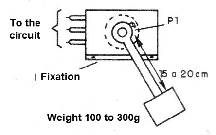
The sensor consists of a common potentiometer built in the position shown in Figure 4.

The pendulum must have a weight that allows the movement of the potentiometer shaft with ease to any change of speed of the car.
Test and Use
To test the appliance, just power it. Turning the potentiometer P1 and adjusting P2 one must obtain a range of positions in which we have none of the four LEDs lit.
In the installation, the ground points are connected to the chassis of the car and the power can be taken from any point of the wiring of the car in which we have 12 V.
The adjustment is made in such a way that in the vertical position of the pendulum we have no LED lit (adjust the position of P1 - structure) for this.
Then, set P2 so that we have all four LEDs lit with a pendulum tilt approximately 60 degrees. Once the adjustment has been made, it is only necessary to use the unit, remembering that higher speed variations (accelerations) require more engine power and therefore means a higher fuel consumption.
Thus, by always using a weighted acceleration one can get more from the engine with lower fuel consumption.
Semiconductors:
Cl1 - U267BE - SID integrated circuit (see text)
LED1 to LEDS - common LEDs - see text
Resistors: (1/8 W, 5%)
R1 - 2.2 k ohms
R3 and R2 - 47 k ohm
P1 - 47 k ohm - potentiometer
P2 - 47 k ohm - trimpot
Capacitors:
C1 - 2,2 uF - electrolytic - see text
C2 - 1000 uF - electrolytic
Miscellaneous:
F1 - 500 mA - fuse
Printed circuit board, assembly boxes, integrated socket,
fuse holder, wires, welding, etc.


