PWM controls have the advantage of high performance and maintenance of torque at low speeds.
See more on the website where we explain this in a whole article (ALM442).
The control we describe uses a high power MOSFET, which can control intense currents, but it needs voltages of at least 5 V to operate, hence we can not use it in motors of less than 6 V.
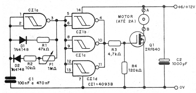
The circuit is based on an oscillator with the 4093 with the active cycle controlled by a potentiometer.
In Figure 1 we have the complete control circuit.

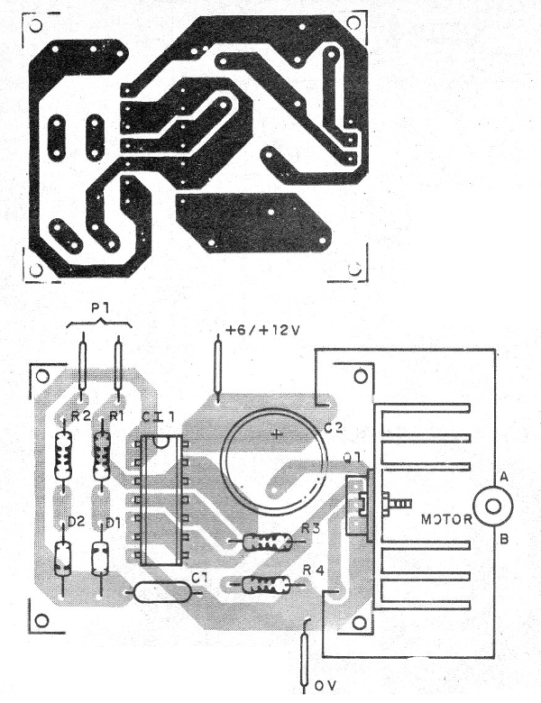
In Figure 2 we have a suggestion of printed circuit board for the assembly.

Any MOSFET works as this component must be equipped with a heatsink according to the motor current.
The resistors are 1/8 W with any tolerance and the capacitor C1 must be tested so that the motor has good control, without vibrations.
The electrolytic capacitor must have higher voltage than that used in the power supply.
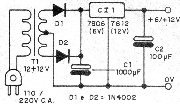
In Figure 3 we have a suggestion of a stabilized source of 6 V or 12 V for currents up to 1 A.

On the assembly, note the position of the integrated circuit and MOSFET as well as the polarity of the diodes and electrolytic capacitor.
CI-1 - 4093 - CMOS integrated circuit
Q1 - IRF640 or equivalent - Power MOSFET
D1, D2 - 1N4148 - silicon diodes
P1 - 1 M ohms - potentiometer
C1 - 100 nF to 470 nF - ceramic or polyester capacitor
C2 - 1000 uF - electrolytic capacitor
R1 - 47 k ohm - resistor - yellow, violet, orange
R2 - 10 k ohm - resistor - brown, black, orange
R3 - 4k7 ohm - resistor - yellow, violet, red
R4 - 120 k ohm - resistor - brown, red, yellow
Miscellaneous:
Printed circuit board, power supply, heat sink, wires, welding, etc.


