We can turn on and off a small engine at regular intervals, thus obtaining the automatic activation of the most diverse mechanisms.
One application is in a small timed fan or in a liquid mixer in the chemistry lab.
Another application is to apply the circuit to our aeroboat making it work automatically at regular intervals.
The circuit can control motors up to 500 mA with voltages from 5 to 12 V.
The activation intervals can be set from a few seconds up to a few minutes.
How it works
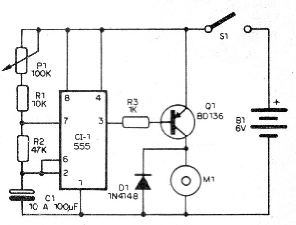
The base of the circuit is a 555 astable where the frequency depends on C1 and the resistors R1 and R2, being adjusted by P1.
C1 can have a wide range of values.
The 555 signal consisting of trips to the high level at regular intervals is applied to the base of a medium power transistor type BD136.
In this circuit, the time the motor is driven depends on R2 and the interval between the drives depends on the setting of P1.
Assembly
The complete diagram of the intermittent motor is shown in Figure 1.

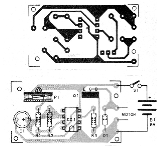
The assembly can be done either in a contact array or on a printed circuit board.
In Figure 2 we give the printed circuit board for this assembly.

On the assembly, note the position of the integrated circuit and the polarity of the motor and diode.
The motor must be turned on so that it rotates in the desired direction.
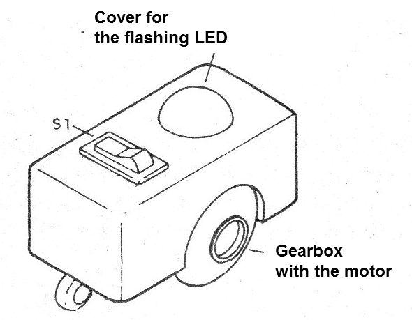
In Figure 3 we have a suggestion of a small robot with intermittent drive controlled by our circuit.

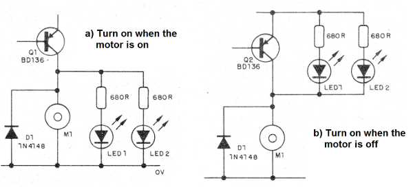
For an LED to light it when the motor is started, the circuit of Figure 4 can be used.

To use this device, simply press S1 and set P1 to run the engine at regular intervals.
To increase the intervals at which it triggers, increase the value of R2.
CI-1 - 555 - integrated circuit
Q1 - BD136 - medium power PNP transistor
D1 - 1N4148 - general purpose diode
M1 - motor up to 500 mA
P1 - 100 k ohm - potentiometer
S1 - Single switch
B1 -5 to 12 V - battery or batteries
C1 - 10 to 100 uF - electrolytic capacitor
R1 - 10k ohm x 1/8 W- resistor - brown, black, orange
R2 - 47 k ohm x 1/8 W - resistor - yellow, violet, orange
R3 - 1k ohm x 1/8 W- resistor - brown, black, red
Miscellaneous:
Printed circuit board, battery holder, assembly box, wires, welding, etc.


