The circuit is very simple and can actually operate with any type of toy with an electric motor of 6 to 15 volts and with a current that does not exceed 2 A. In this, besides the electric trains, we can frame autoramas.
No modification will be required in the original control, since the system can be interleaved between this and the line, as shown in Figure 1.
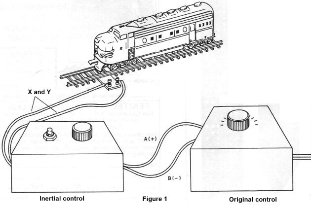
The potentiometer of our control will be used for our operation, being the potentiometer of the original control in the position of maximum speed.
HOW IT WORKS
Two power transistors are used in the Darlington configuration as an electronic rheostat.
The base current of the first transistor (Q2 in the diagram) determines the current to be applied to the motor, in this case, through the collector of Q1.
Since this base current is very small, we can obtain an automatic variation of its intensity using RC networks with components of relatively low values.
Thus, the potentiometer which controls the base current of the Darlington pair has a delay network formed by the resistors R1 and R2 and the capacitor C2.
When we open the speed control, which is P1, the current does not immediately rise in value on the basis of Q2, since it is necessary first to have the charge of C2 through the resistor R1. The practical effect is that the circuit does not respond to fast speed variations imposed by P1, which means that there is a limit to the acceleration of the motor used as a load.
The curve in Figure 2 illustrates what happens.
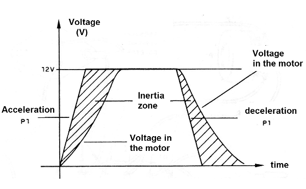
A rise in voltage at the P1 slider is not accompanied by an immediate rise in load voltage.
In the same curve we have the effect of the deceleration with inertia. The train also does not stop immediately when we act on the control in this regard.
When the P1 cursor is brought to the earth side, with the volt reduced to zero, the capacitor C2 still takes some time to supply the base current of Q2. The transistors amplify this current and the motor gradually loses its speed until it stops.
With the speed changing, the inertia effect also holds for the same reason.
An interesting feature which this circuit has is the emergency stop, which is done by S1. When pressing this switch, the voltage at C2 drops to zero, with the immediate stop of the motor.
ASSEMBLY
In Figure 3 we have the complete diagram of the speed control.
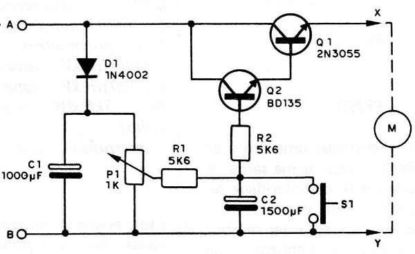
As we can see all the components are common. In Figure 4 we give the version on a terminal stgrip, which can be considered the most recommended, since there is a reduced number of components and lack of a compact design.
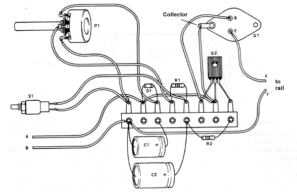
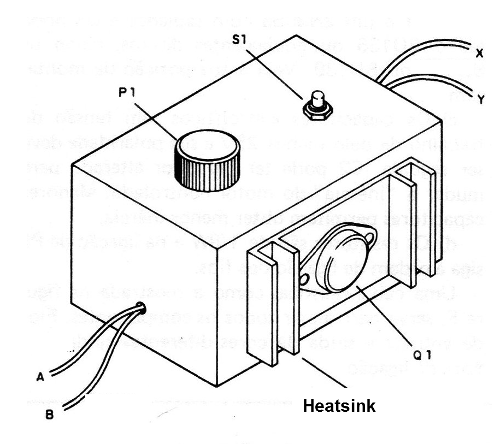
Transistor Q1 should be attached to a heat radiator, as shown in Figure 5, especially if the controlled train, or the motors, require currents above 500 mA.
In the assembly, there are few precautions which should be taken, all listed below:
a) The diode D1 has the right polarity and may be, in addition to 1N4002, any equivalent, such as 1N4004, 1N4007 or BY127.
b) Q1 is a 2N3055 with a radiator and Q2 can be BD135 or direct equivalents, such as BD137 or BD139. See its assembled position.
c) The electrolytic capacitors have a working voltage of at least 25 V and their polarity must be followed. C2 may have its value changed to change the "inertia" of the controlled motor. Smaller capacitors allow lower inertia.
d) The resistors are 1/8W and in the P1 connection follow the order of connection of the wires.
A plastic box, such as that shown in Figure 5, works to house all the components. Different color input and output wires help at the connection time.
TEST AND USE
To test, you can employ a 12 V power supply and a bulb or motor connected to the output. The source will be connected to A and B, with the polarity followed (A = positive and B = negative).
When acting on P1, the lamp should have its brightness changed with certain inertia, while with the motor will change its speed.
To use, it is only interleaving the control between the original transformer, whose potentiometer must be kept at maximum, and the line, following the polarity.
Q1 - 2N3055 - power transistor
Q2 - BD135 - power transistor
D1 - 1N4002 or equivalent - silicon diode
P1 – 1k - single potentiometer
C1 - 1000 uF x 25 V - electrolytic capacitor
C2 – 1 500 uF x 25 V - electrolytic capacitor
R1, R2 - 5k6 x 1/8 W - resistors (green, blue, red)
S1 - pressure switch (doorbell button)
Miscellaneous: a terminal bridge, heat radiator, screws, wires, button for the pot, box, etc.


